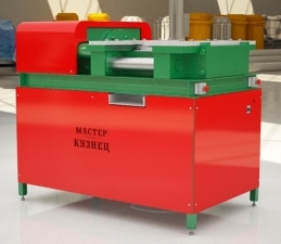
MASTER KUZNEC UNIVERSAL PROFESSIONAL ELECTRO-HYDRAULIC PRESS FOR HAMMER FORGING PRODUCTION
Technical Certificate
Zarechny
1. Purpose
Universal professional electro-hydraulic press Master Blacksmith (hereinafter the Press) for industrial purposes is intended for manufacturing hammer forgings of long profile steel (square, strip, round) with their subsequent assembly (welding) into finished artistic products (gates, fences, grates, etc.). The press is electric one with foot control. It performs ornamental bending of sheet metal (without heating), applying texture to rolled stock surfaces, heating and various spreading actions to form decorative metal items.
2. General machine arrangement
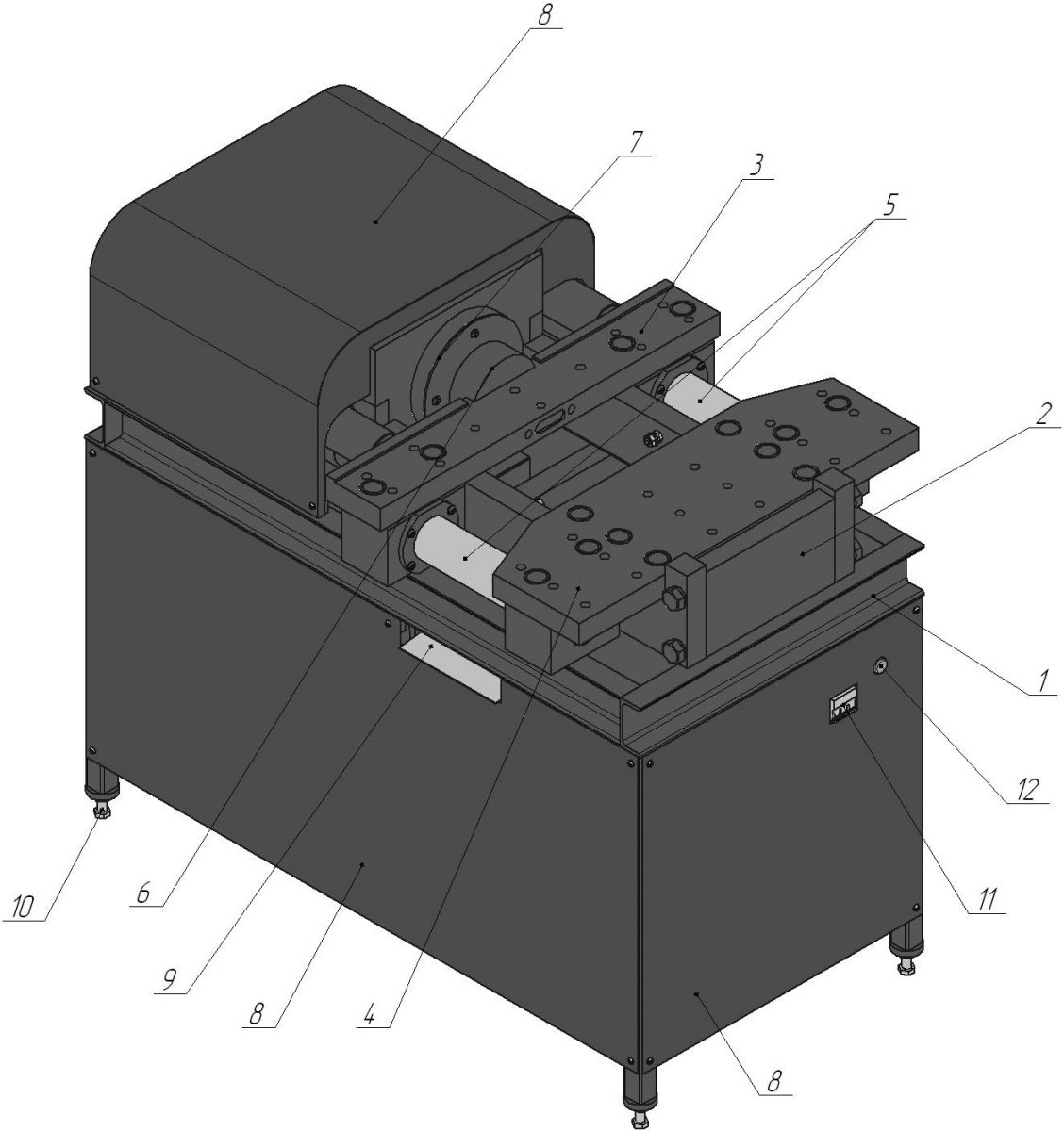
Fig. 1. General machine arrangement
1 – Bed; 2 – Active unit; 3 – Sliding table; 4 – Fixed table; 5 – Way; 6 – Faceplate; 7 – Hydraulic power cylinder; 8 – Protective covers; 9 – Debris; 10 – Set bolt; 11 – Circuit breaker; 12 – Voltage indicator.
3. Safety measures when working on the machine
3.1. Read the operating instructions and inspect the machine prior to operation in order to ensure proper and safe use of all its functions.
3.2. The manufacturer has priority on the production of the machine, improves its design and has the right to make changes that not affect its performance.
3.3. Machine operation is allowed with the RCD (residual current device) installed in the network. Electricians having minimum 3 electrical safety qualification must install and connect the machine to the network.
3.4. The machine housing must be grounded using a special conductor with a section not less the phase wire.
3.5. It is prohibited to:
- operate the machine without grounding;
- work with the open circuit breaker cover, side and top panels of the machine;
- move the machine connected to the network;
- put objects and tools on the machine body;
- run the machine at high voltage (more than 10 V);
- operate the machine in explosive or chemically active environment damaging metal and insulation;
- operate the machine in high humidity conditions (more than 80 %), as well as outdoors.
3.6. Take care to protect the machine against blows, overloads, dirt and petroleum product exposure when operating.
3.7. Switch off the machine using the circuit breaker in case of a sudden stop (due to the voltage loss, seizure of moving parts, etc.).
4. Preparing the machine to operation
4.1. In case of machine transportation or storage in high humidity or low temperature conditions, keep it at the temperature of 20 ± 5°C for 5 hours.
Range of working temperatures: +5 to + 40 °C
4.2. Machine start procedure:
- make sure that the voltage in the mains supply corresponds to the specifications and does not exceed it by more than 10 V;
- set the circuit breaker to the "off" position;
- inspect and ensure the proper insulation of the power cable and connect it to circuit breaker terminals in the correct sequence.
Warning!
Ensure the direction of motor rotation is clockwise during the phase connection.
- connect the power cable to the network;
- connect the drive pedal to the connector (located under the protective cover);
- set the circuit breaker in the "on" position;
- ensure the forward movement of the hydraulic power cylinder rod by pressing the drive pedal.
4.3. Machine stop procedure:
- stop pressing the drive pedal, then the actuating hydraulic cylinder rod will return to the initial position;
- remove any metal blanks from machine actuators;
- set the circuit breaker to the "off" position;
- unplug the network cable from the mains.
Warning!
Reset the press not earlier than 30 seconds after shutdown.
5. Machine operating principle
First of all, the machine is prepared to operation depending on what kind of texture or decorative item is needed.
Select the same die pairs and mount them on the ways in case of forming and texture applying operations, and on the tables when performing decorative bending (see installation and operation procedure below).
Use the pedal to actuate the motor connected to the gear pump via clutches. It supplies oil from the hydraulic tank to the pump to build pressure and transmit it into the parallel hydraulic cylinder. The hydraulic cylinder rod starts translational movement transmitted to the sliding table with the dies fixed on it (for forming or texture applying operations) or the punch (for decorative bending operations). The second die part is rigidly attached to the fixed table. Then the dies approach each other with the workpiece set on the adjustable stop pre-set to the desired position. The dies begin compressing the workpiece in certain forms, while the operator must rotate the workpiece or pull/push it after each compression depending on the result required. The metal changes its shape to achieve a certain pattern corresponding to the outer die pattern.
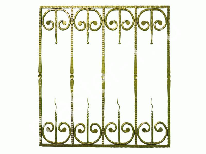
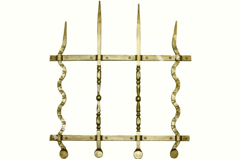
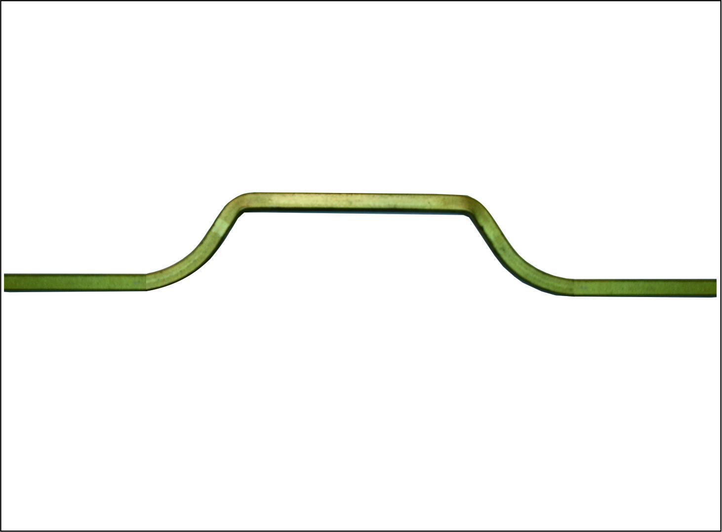
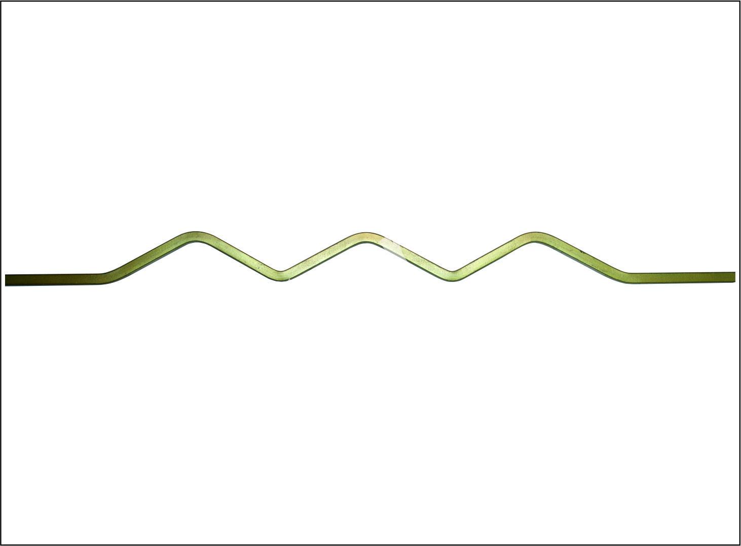
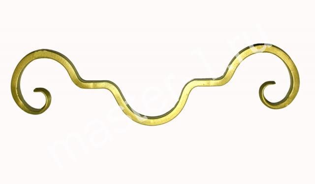
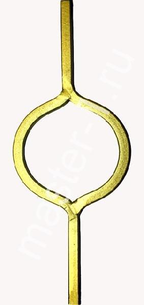
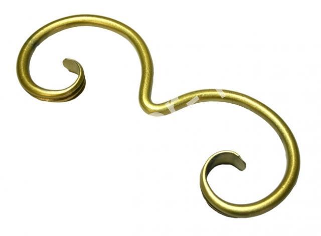
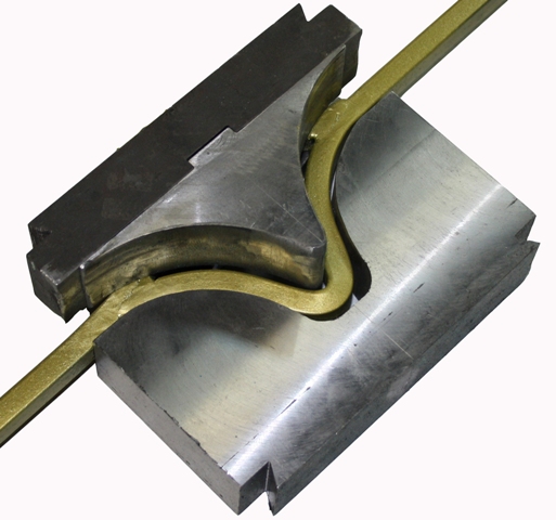
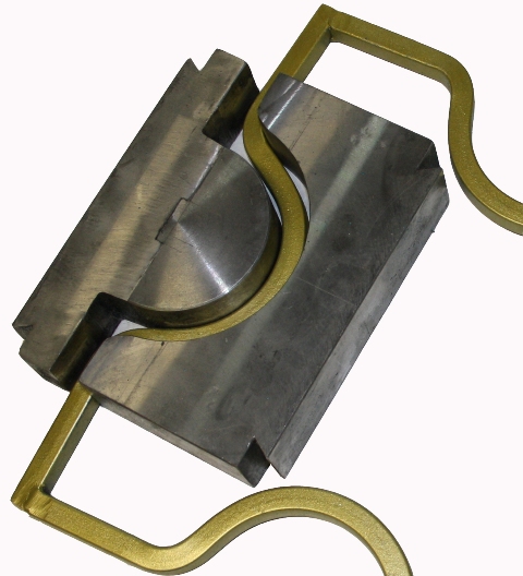
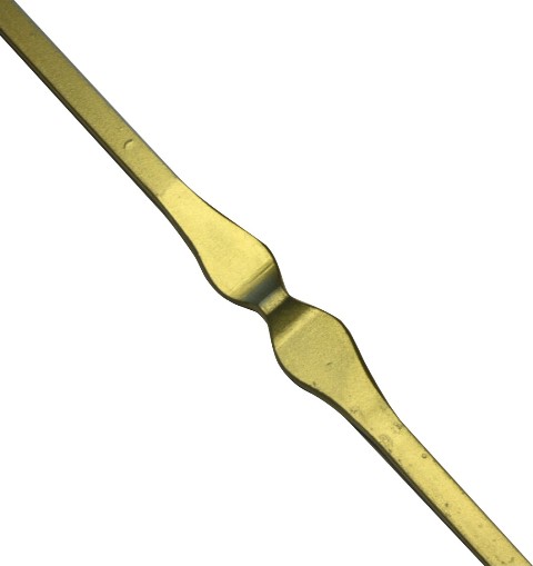
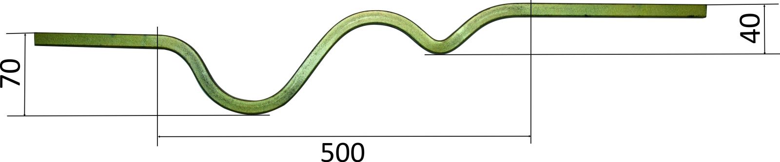
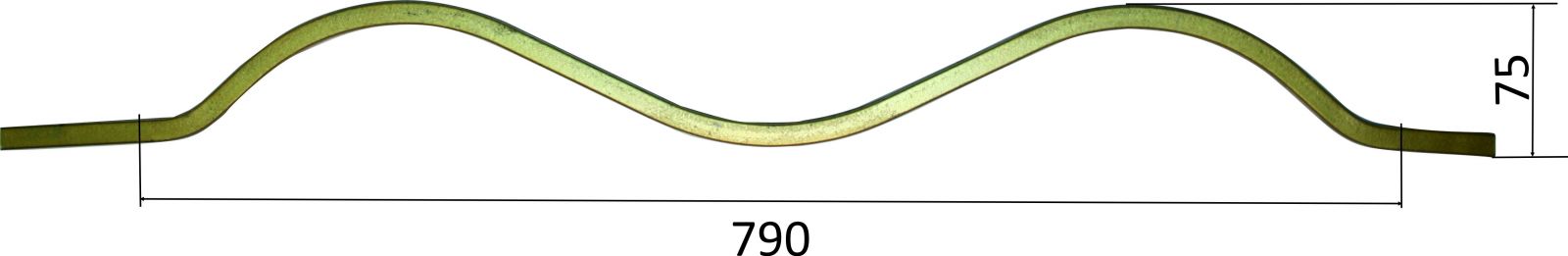
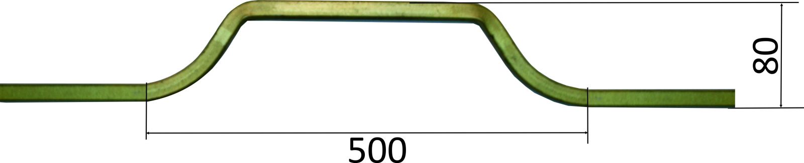
6. Bar stock bending operation
Follow these steps for bar stock bending:
6.1. Cut the bar to a required length (use Steel 0 - 3 only).
6.2. Install additional devices (see Fig. 2) according to marks on the die.
6.3. Place the workpiece on the fixed table (see Fig. 3).
6.4. Press the pedal and hold it until you obtain a desired item.
Note: it is recommended to grease the working surfaces of the punch and die with "Litol" or "Solidol" lubricants in order to reduce punch and die wear and work hardening on the finished item.
Warning!
To avoid injury during the bending operation it is NOT REQUIRED to HOLD THE WORKPIECE – it must be in a free state when the sliding table is moving.
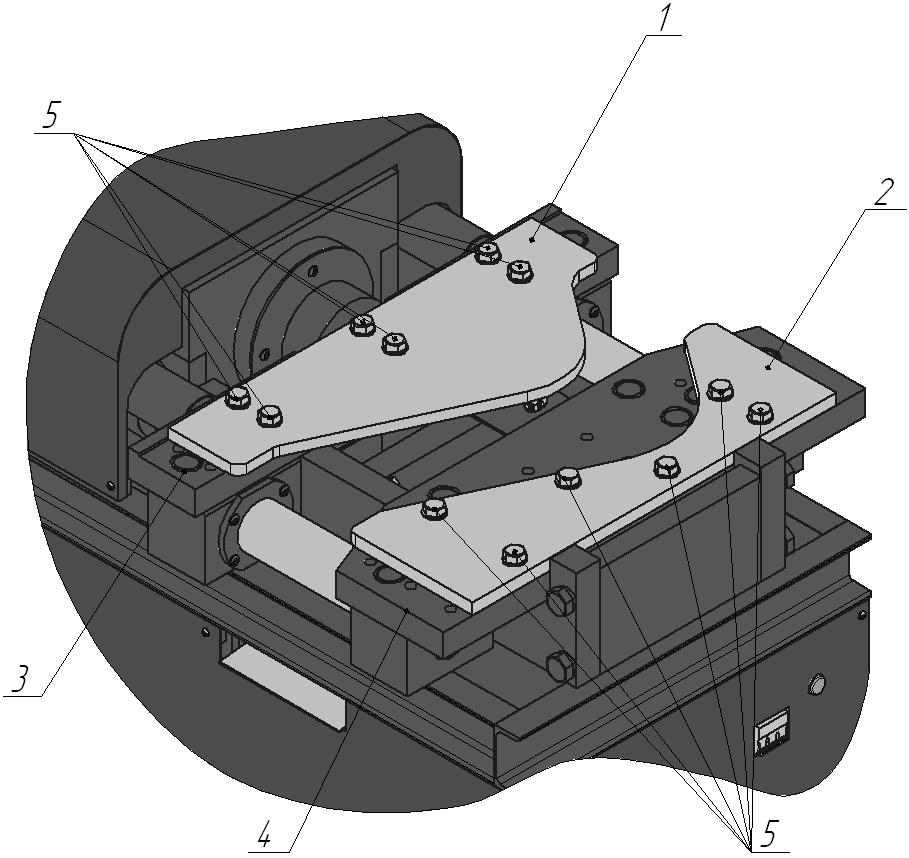
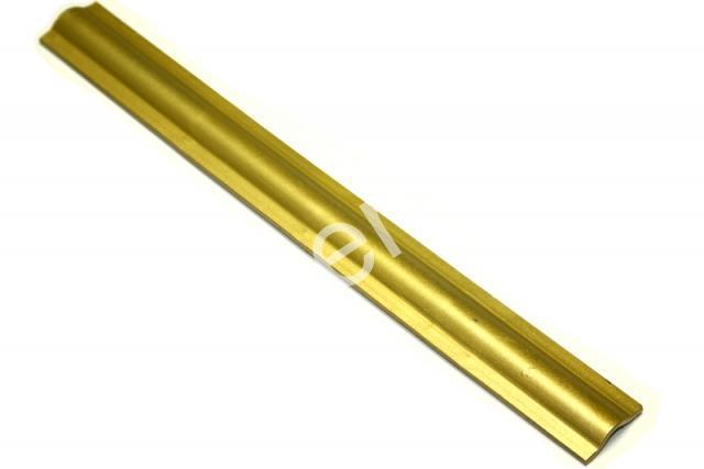
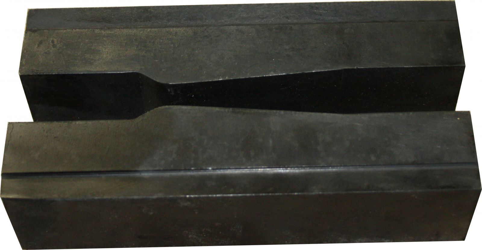
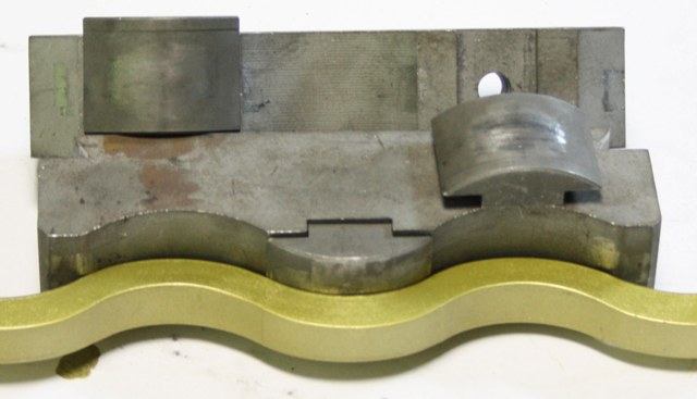
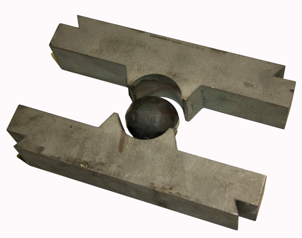
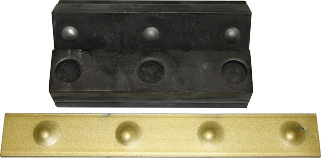
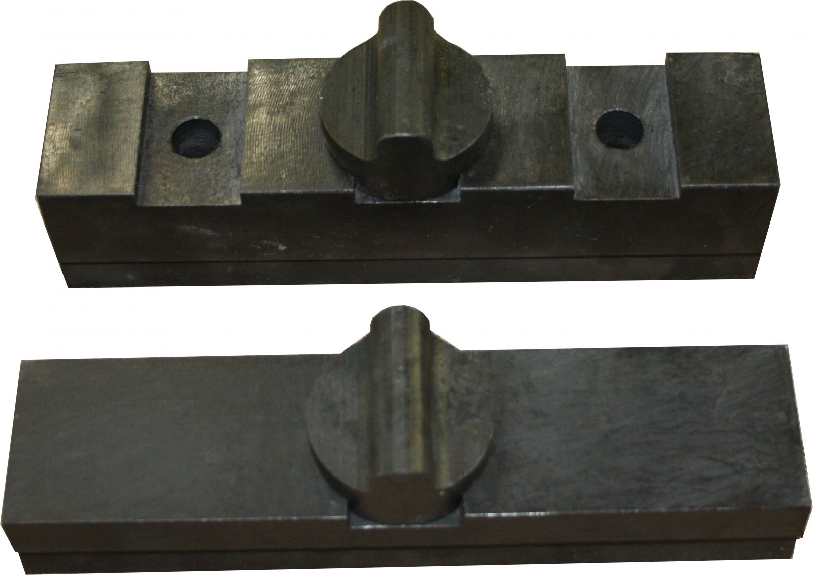
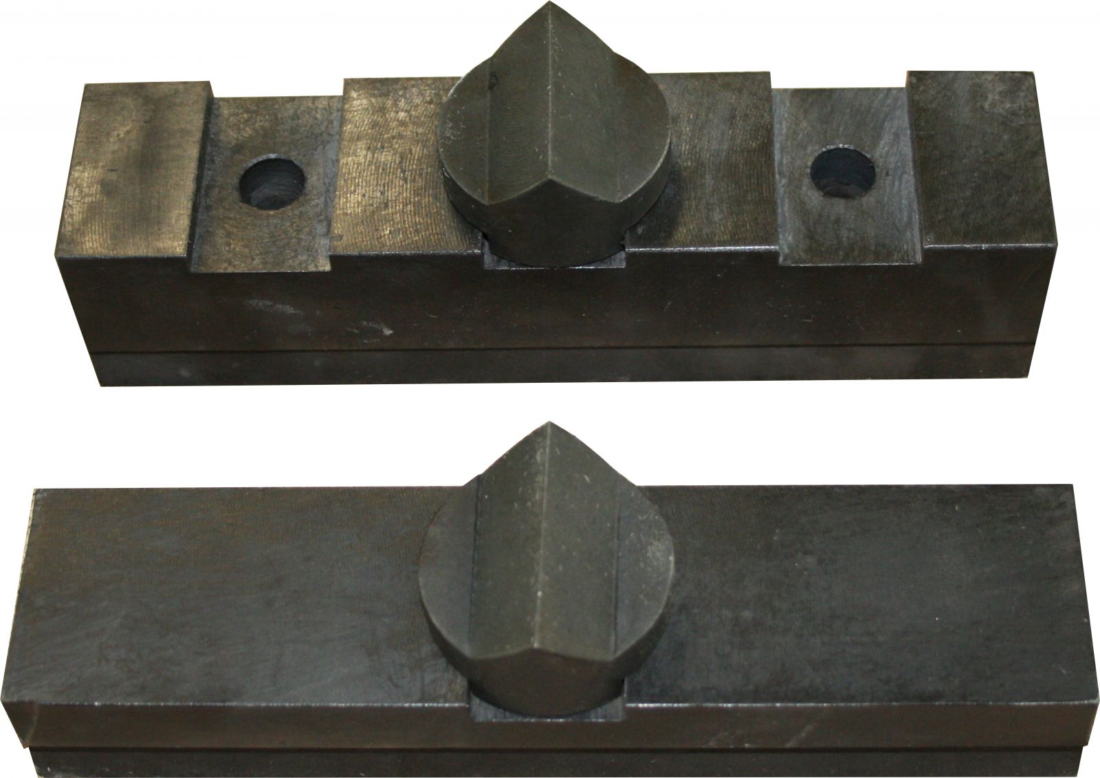
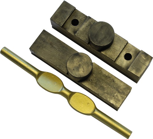
Fig. 2. Installation of additional devices for bar stock bending
1 – Punch; 2 – Die; 3 – Sliding table; 4 – Fixed table; 5 – М18х1.5-40 bolt, 18 washer.
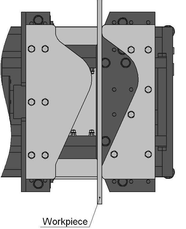
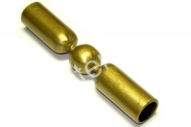
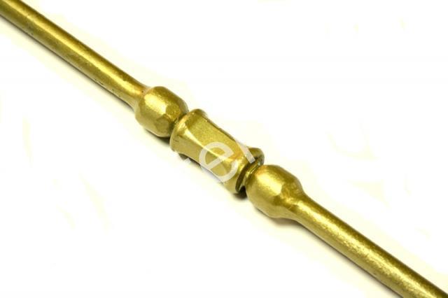
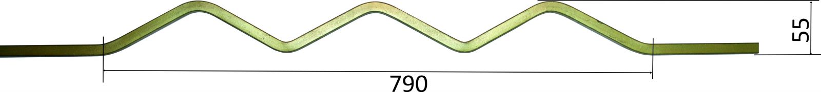
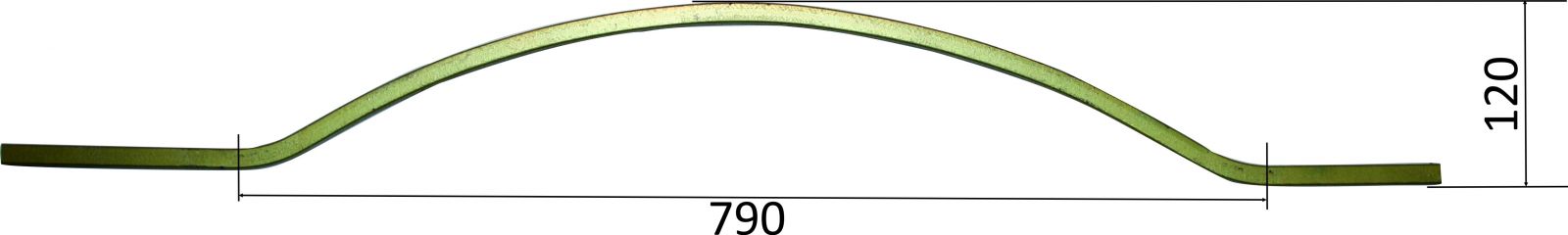
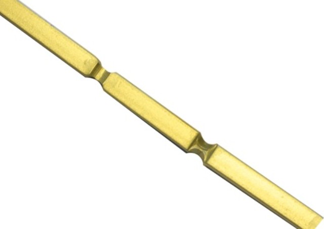
Fig. 3. Workpiece installation diagram
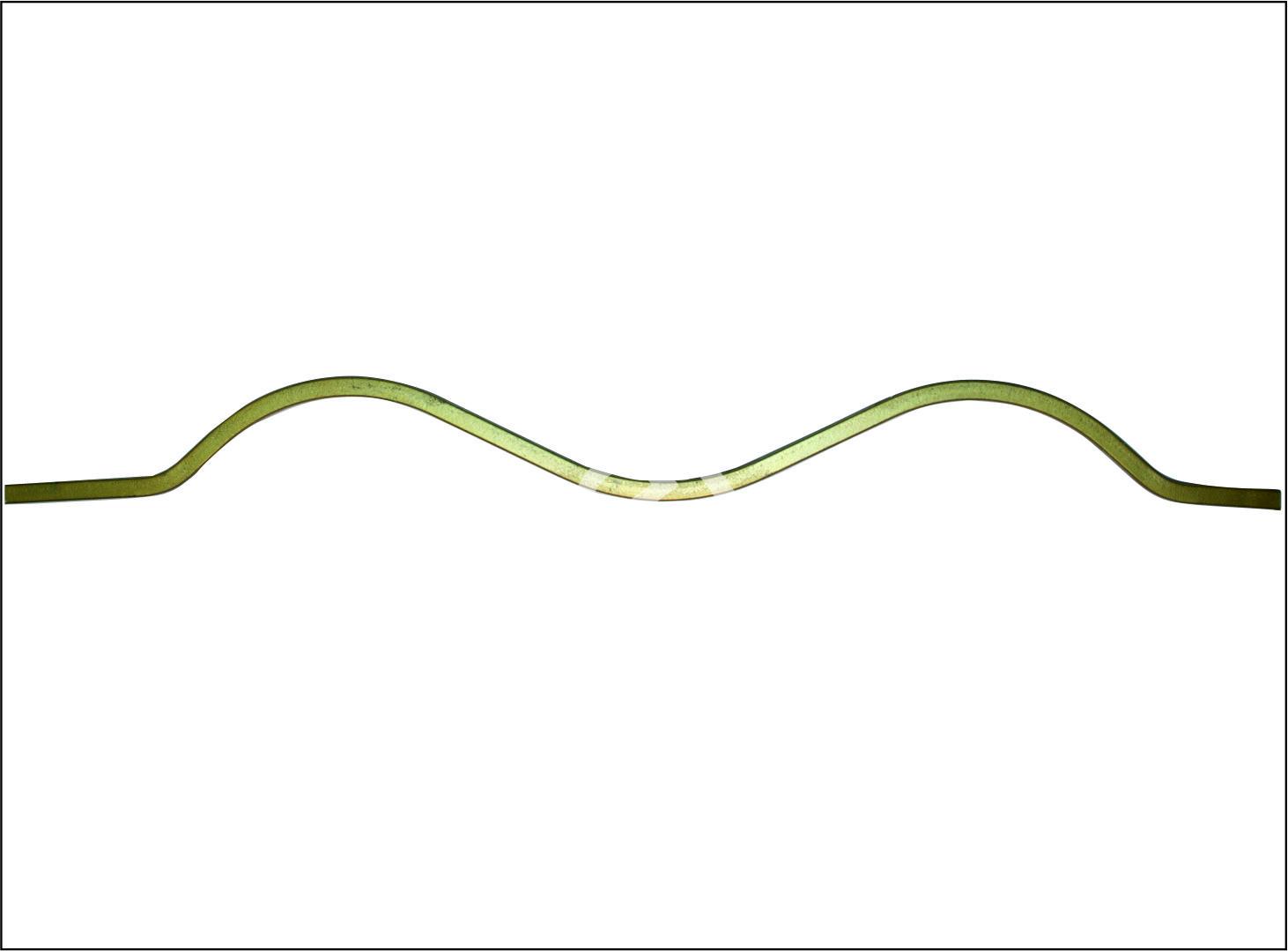
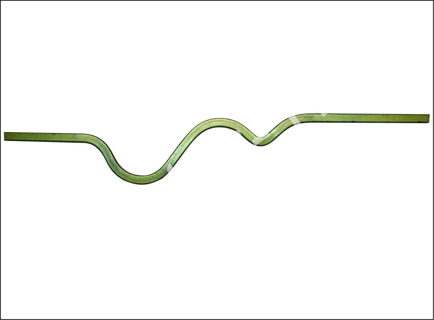
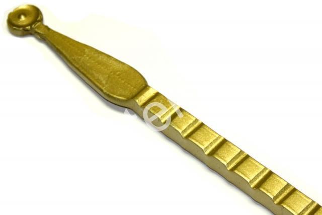
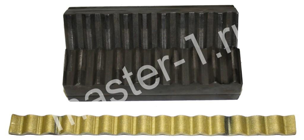
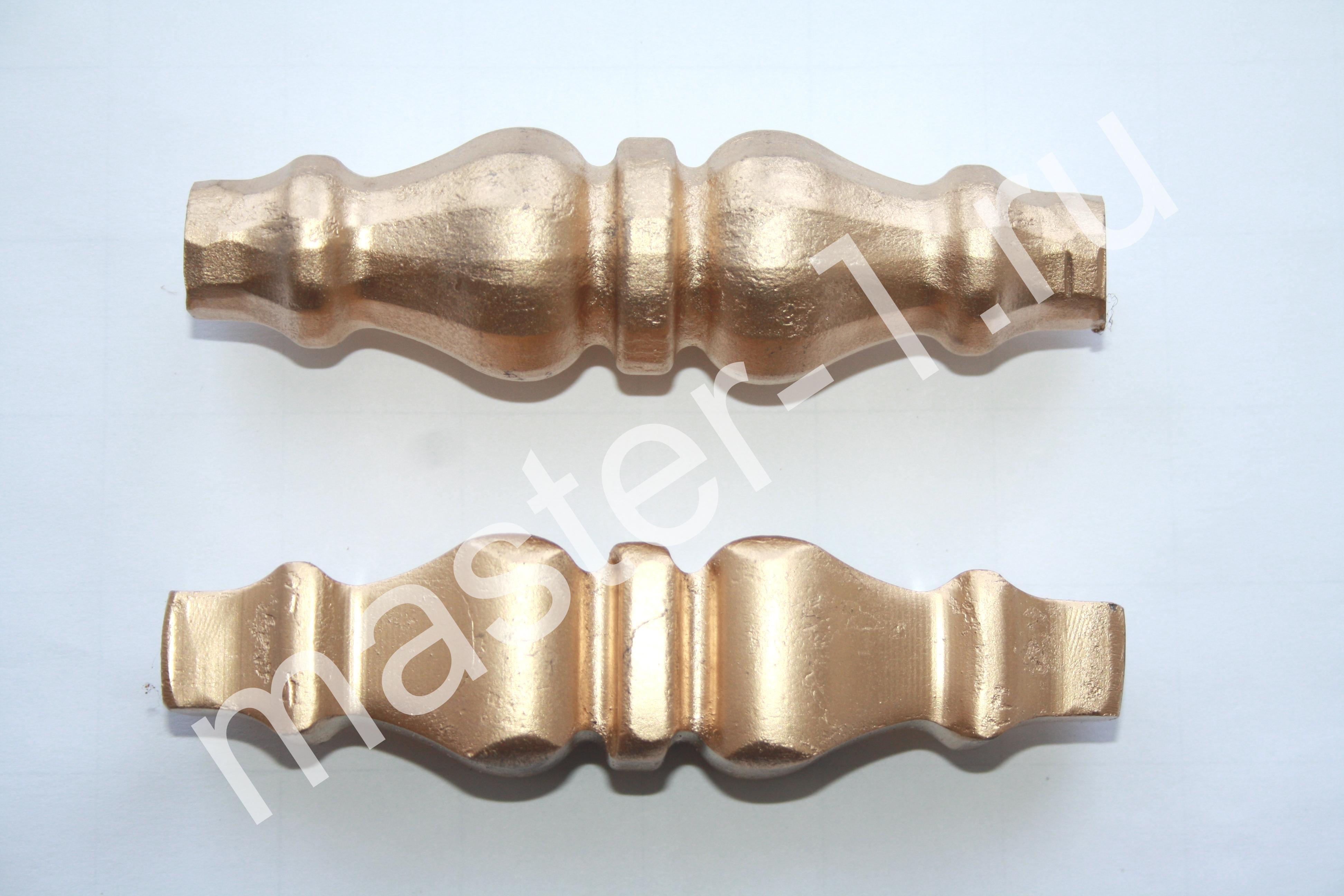
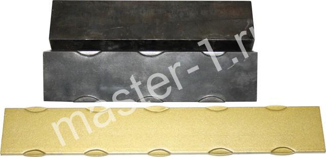
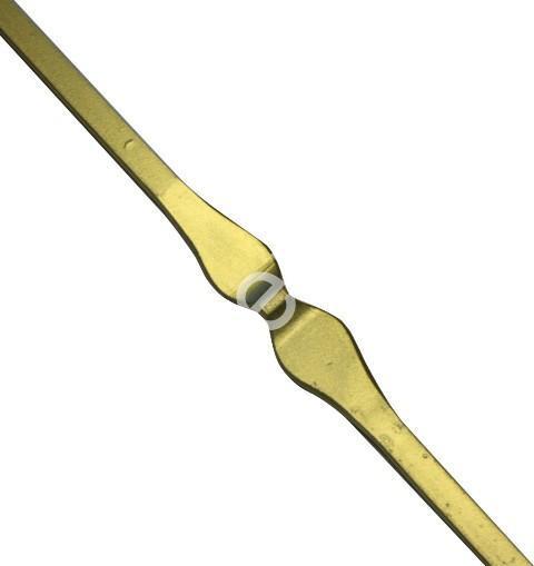
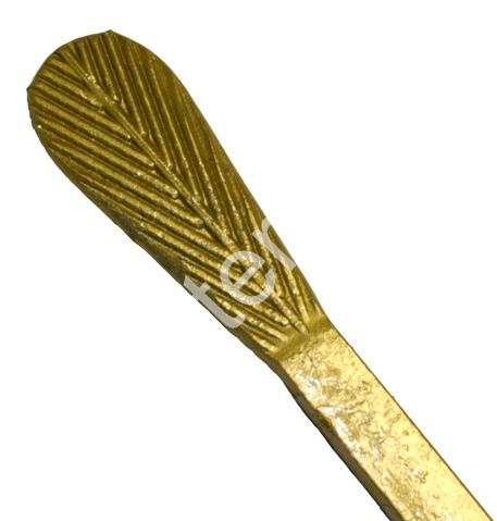
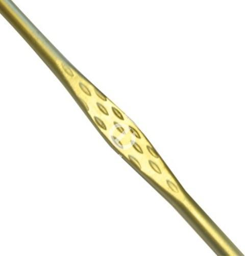
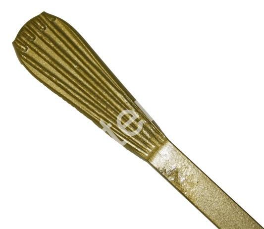
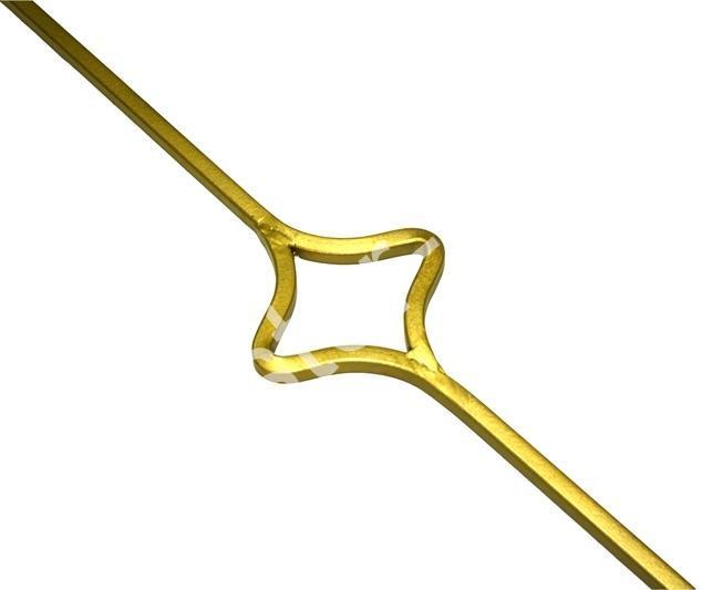
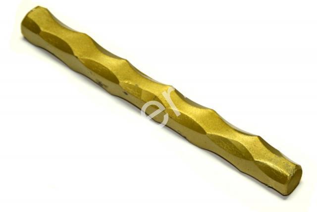
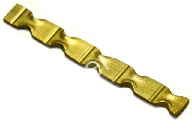
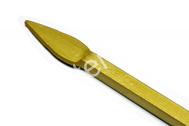
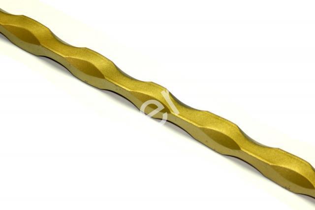
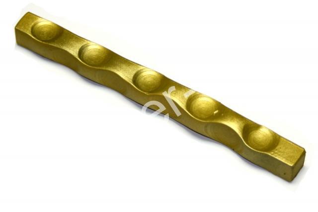
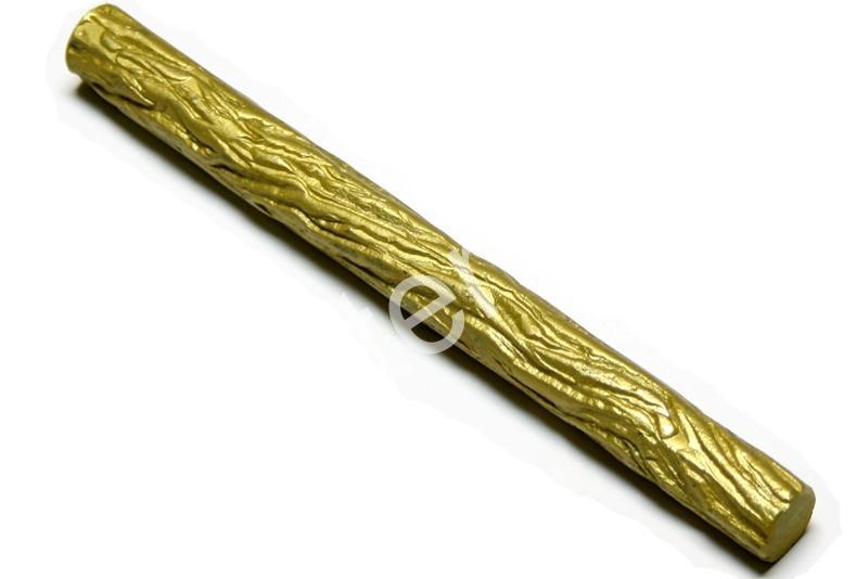
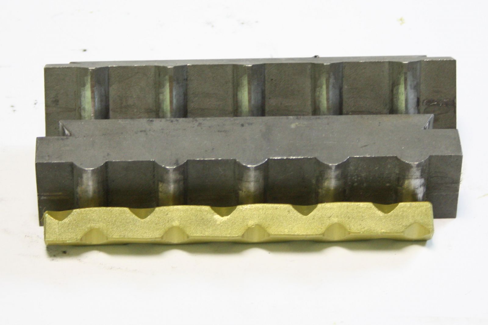
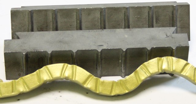
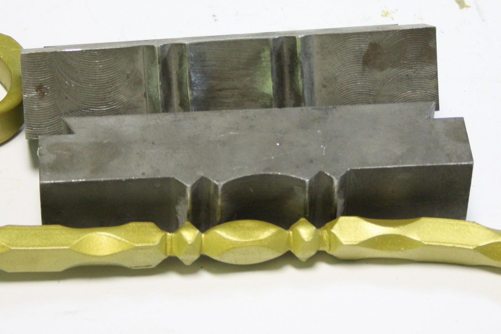
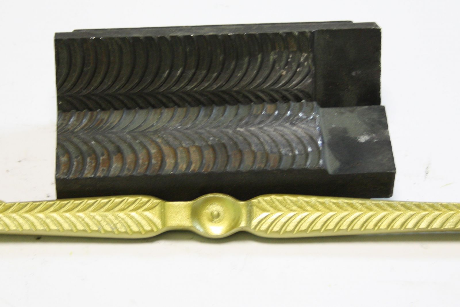
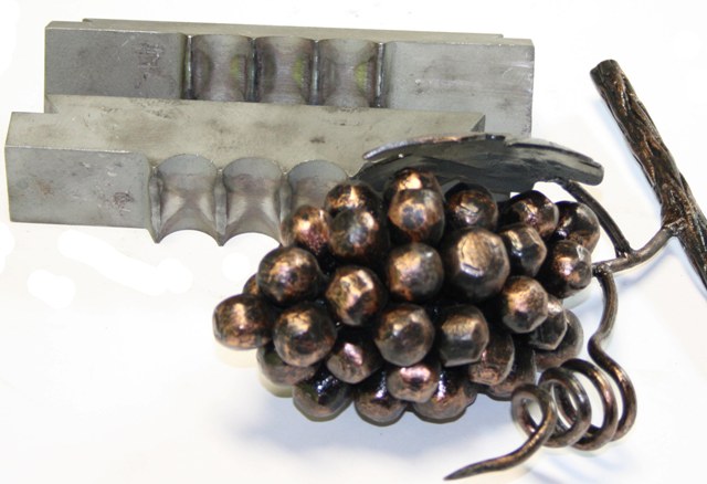
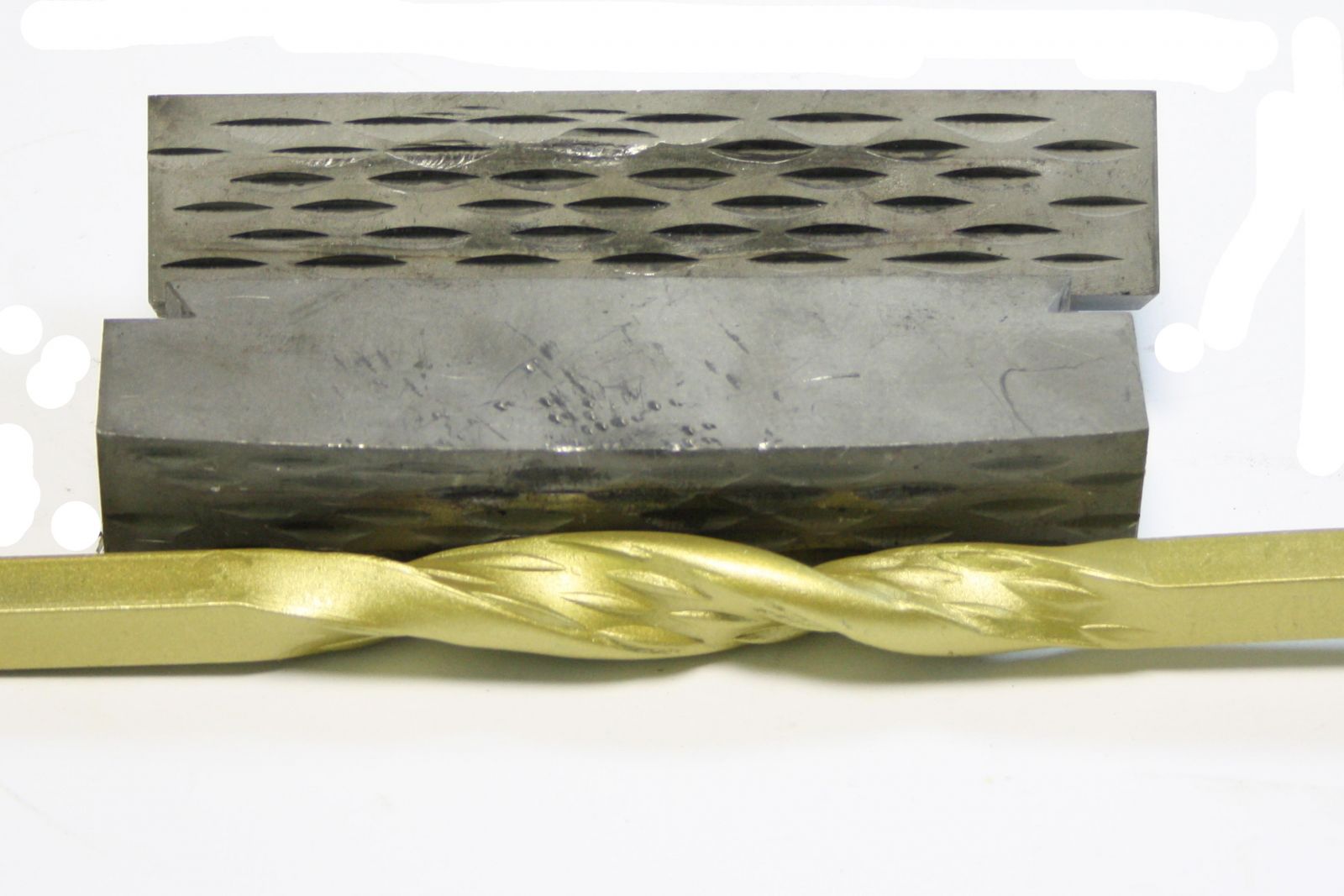
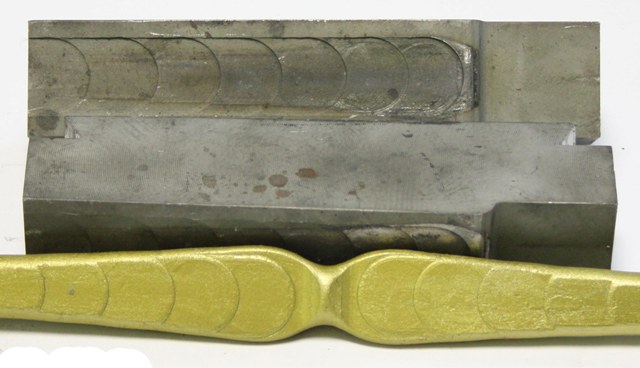
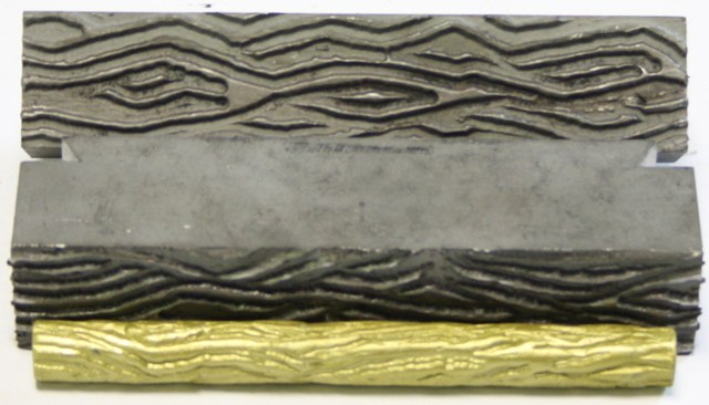
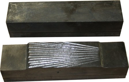
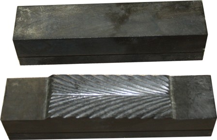
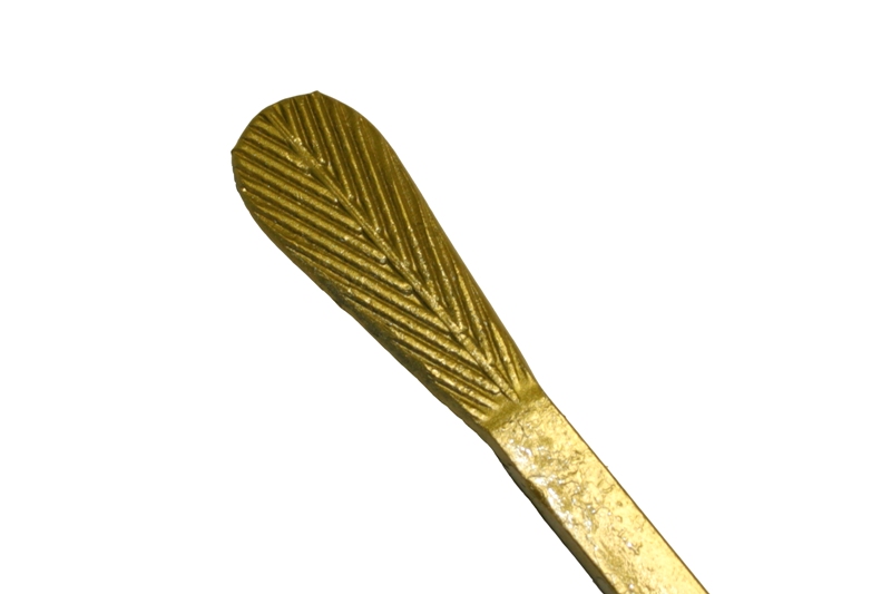
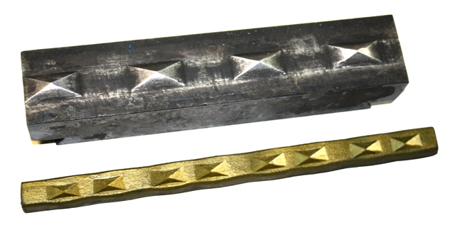
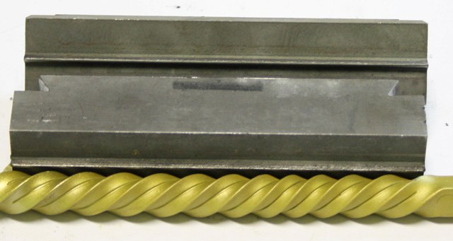
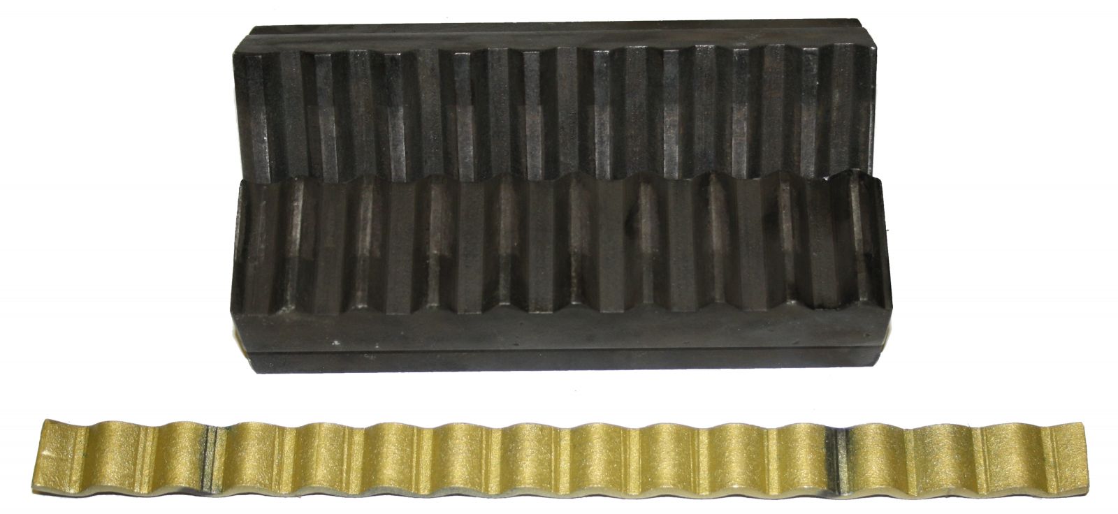
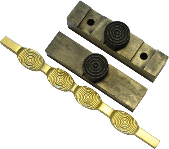
7. Applying texture to the bar stock and forming operations
Depending on the purpose and finished product, dies are divided into forming ones and that used for applying texture on bar stock.
The procedure of mounting devices and operation steps are identical for the operations of forming and applying texture on bars.
To perform these operations proceed as follows:
7.1. Cut the workpiece to the required length (use Steel 0-3 only).
7.2. Install additional devices as shown in Fig.4.
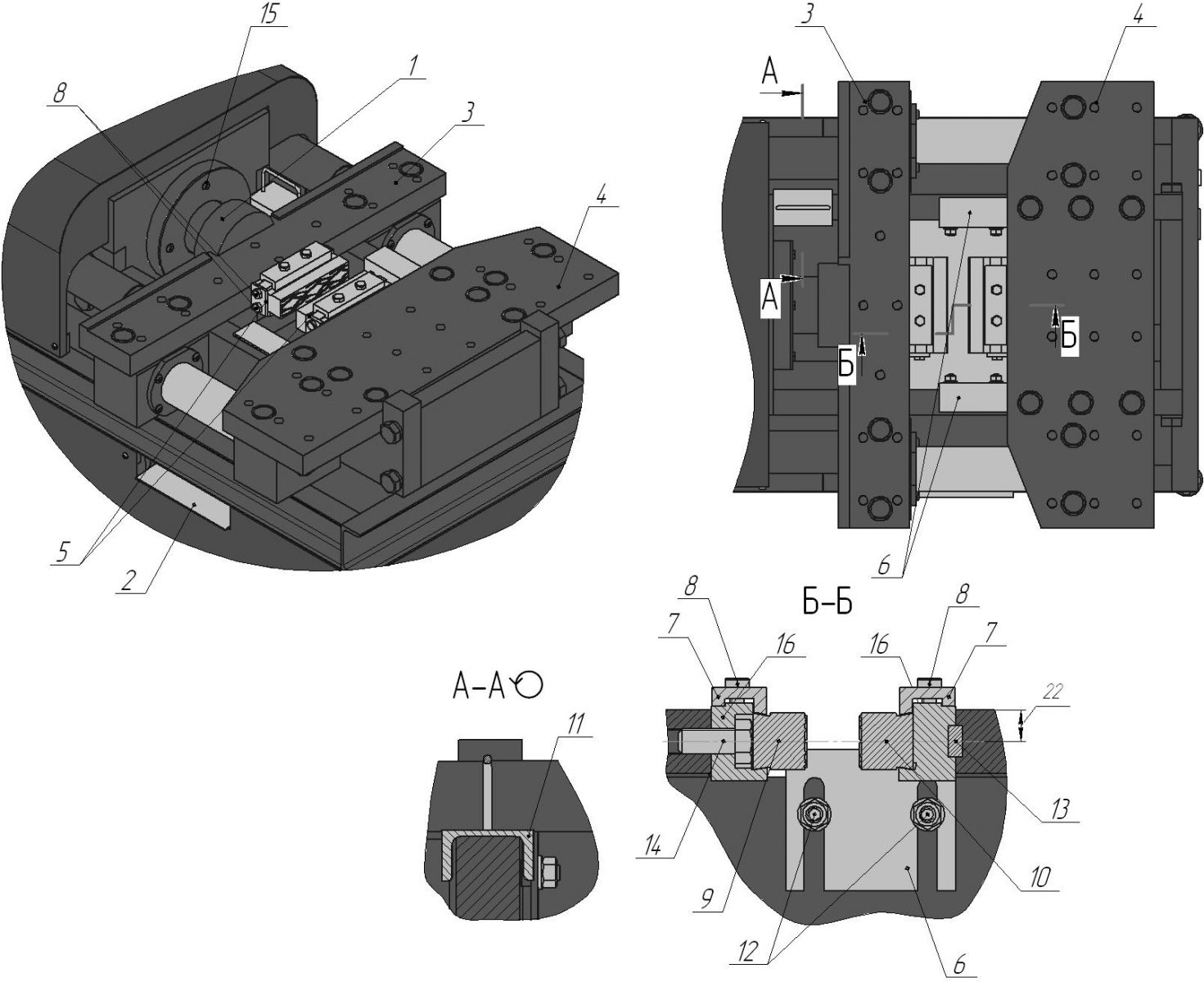
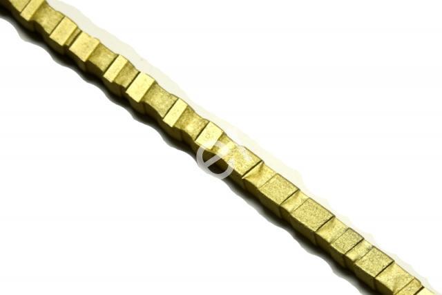
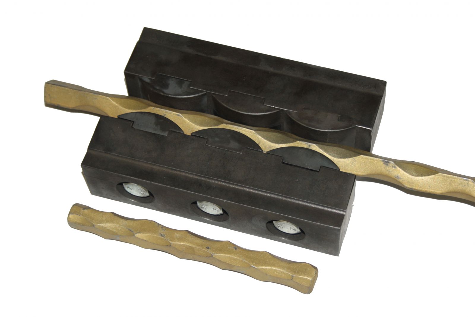
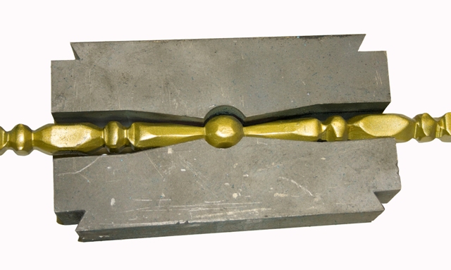
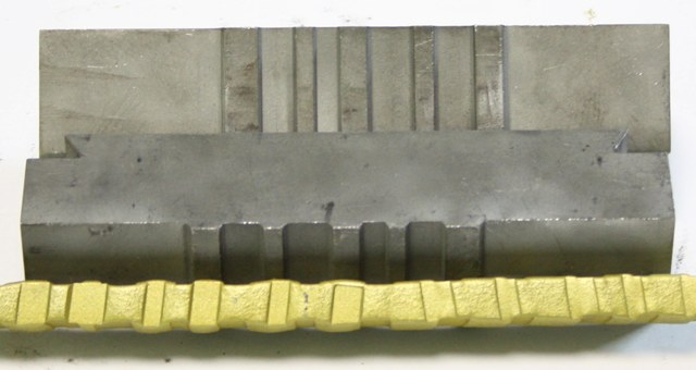
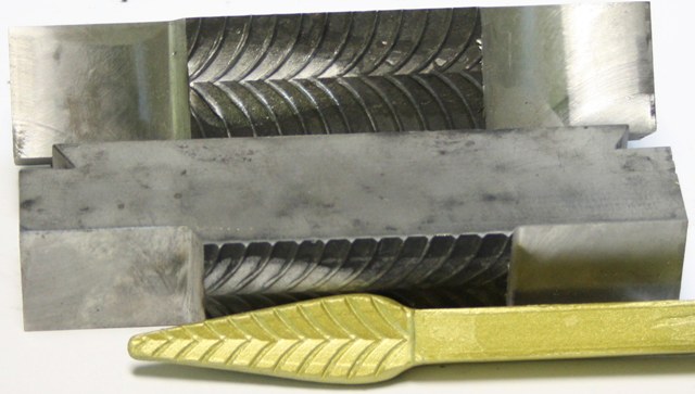
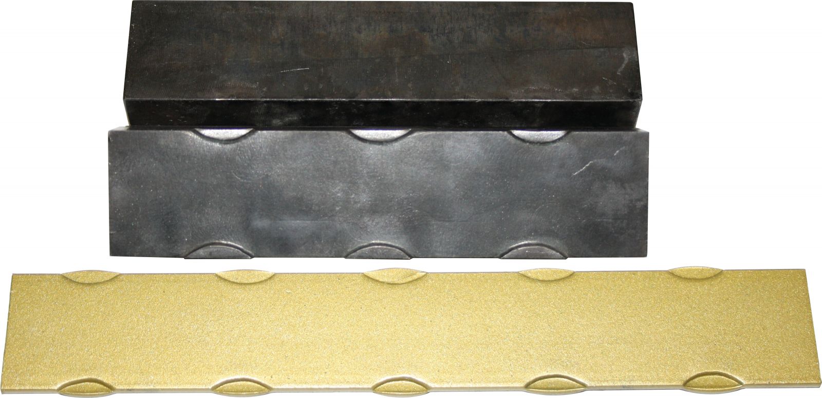
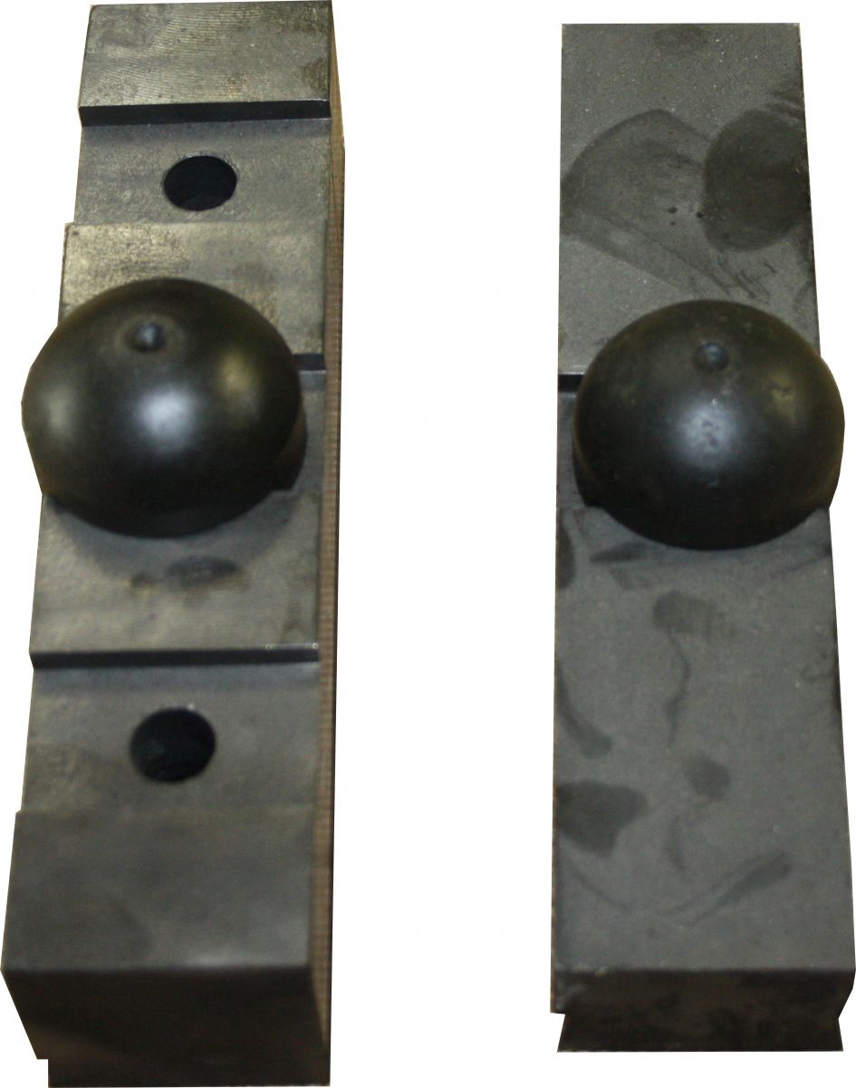
Fig. 4. Installation of additional devices for forming operations and applying texture on bar stock
1 – Faceplate; 2 – Debris; 3 – Sliding table; 4 – Fixed table; 5 – Stop; 6 – Stop; 7 – Stop; 8 – М10х20 bolt; 9 – Die; 10 – Mating die; 11 – Insert; 12 – М12 nut, 12 washer; 13 – Pin; 14 – М18х1,5-40 bolt; 15 – Power hydraulic cylinder; 16 – Guide die.
Note: install dies against stop 5; insert 11 is used for convenient handling of 8-16 section rolled steel; it is mounted after moving sliding table 3, between the wall of the end of the working unit and the end of the sliding table as shown in Fig. 4.
Warning!
It is not recommended to install a pair of dies with different patterns.
When performing hot operations, observe the operation mode (30 minutes work / 30 minutes break ) to avoid removing the hardening (self-tempering) of die steel.
7.1. Adjust stops 6 relative to bar workpiece section; refer to Fig. 4 for the distance to the die center.
7.2. Position the workpiece between dies 9 and 10 at stops 6.
7.3. Press the pedal and hold it until you obtain the item.
8. Machine maintenance
Perform the following checks when operating the machine:
8.1. Verify the integrity of the grounding wires and power supply cable – daily;
8.2. Check the reliability of actuator fastening on the machine – daily;
8.3. Check wire insulation resistance (not less than 2.5 M?) – twice a year;
8.4. Check the oil level in the oil tank (VMG3) as shown in Fig. 5 – once a month;
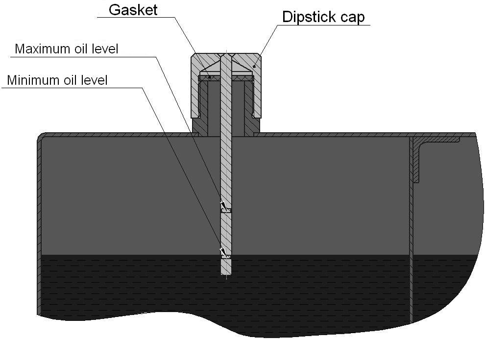
Fig. 5. Checking the oil level in the oil tank
8.5. Inspect and replace the oil filter (see Fig. 6) – every six months;
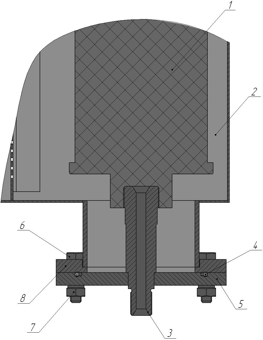
Fig. 6. Oil filter installation
1 – Oil filter CA 200 M60 N (МРА 075 G1 M60); 2 – Oil tank; 3 – Nozzle; 4 – O-ring; 5 – Removable flange; 6 – М10х40 bolt; 7 – М10 nut, 10 washer; 8 – Fixed flange.
8.6. Lubricate ways 5 (Fig. 1) with oil – daily, and protect them from dirt, scale, etc.
8.7. Fill the cavity by injection through grease fittings (Fig. 7) – once a month.
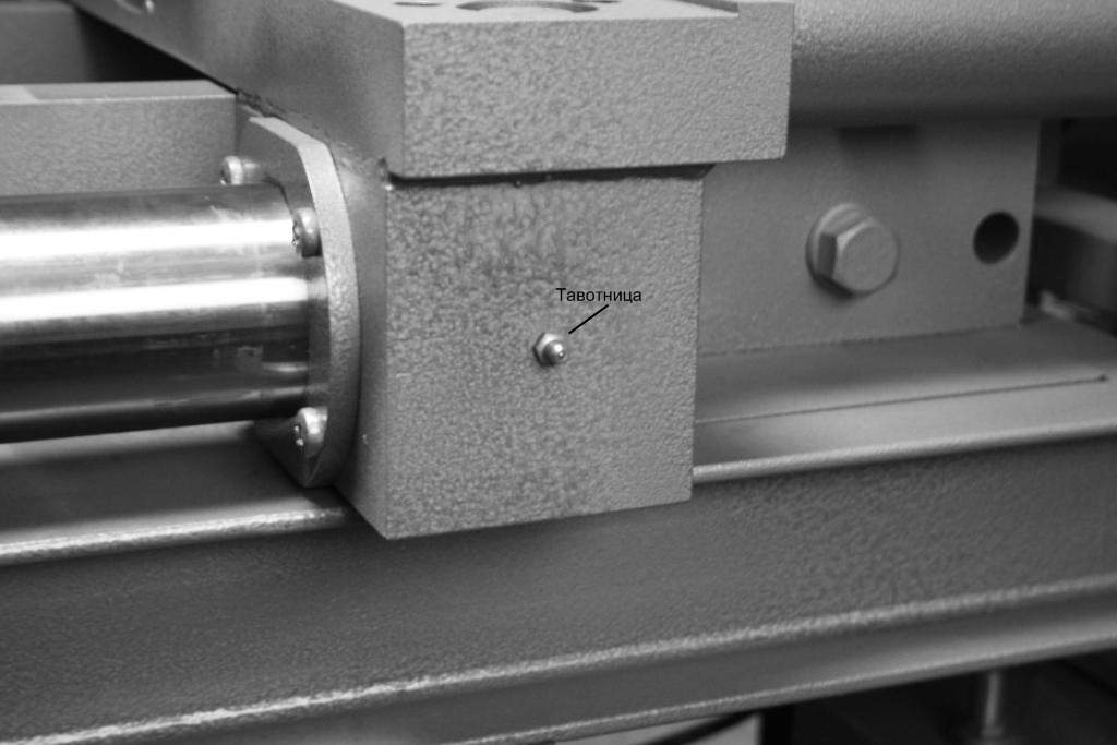 Grease fitting
9. Manufacturer’s warranty
9.1. The warranty period is 12 (twelve) months mechanical parts and tools for hot and cold forging (dies, templates, rolls, rollers, clamps, faceplates, etc.) from the date of Equipment transfer to the Buyer.
9.2. The manufacturer assumes no warranty if the Buyer fails to observe equipment operation rules provided in this manual.
Acceptance Certificate
Electro-hydraulic press Master Blacksmith
Serial Number______________ is manufactured and accepted in accordance with mandatory requirements of state standards, applicable technical documentation and classified as fit for service.
Date_________________ Signature______________
USER MEMO FOR GAS FORGE
Fig. 8 General gas forge diagram
1 – Table; 2 – Forge, 3 – Nozzle; 4 – Adjustment bolt; 5 – Workpiece.
1. Connect the gas forge burner in the following order:
- Direct burner inlet is designed to supply propane from the cylinder (or central gas main). It is performed by attaching a hose to the burner (using a nipple) and to the cylinder (using a special adjustable propane reducer).
- Side burner inlet is intended for feeding compressed air from the compressor (250-400 L/min capacity) or central compressed-air main through the hose.
- Furnace burner is adjustable in its vertical position depending on the torch length (fixing with side screws).
2. Operating procedure using the gas forge:
- Install the furnace on the furnace table, adjust the height of the torch and fix it with bolts.
- Open two ejector holes on the gas burner inlet (move the rubber ring to the side).
- Ignite a piece of paper (or wooden stick) and put it in the furnace chamber with the gas and compressed air stopped.
- Open the valve with gas (0.05 to 0.1 atm).
- Supply compressed air after burner ignition.
- Adjust the torch flame (bright blue).
- Adjust the flame by adjusting the gas or compressed air flow rate after establishing a stable torch flame and torch heating (1-2 min).
- Put the ends of the workpieces (round, square bars) in the furnace chamber for 3-4 minutes until the desired temperature is reached (800-900 ?C to yellow or bright orange color).
- Close the propane and compressed air supply inlet when the gas forge operation is finished.
Warning! Follow safety rules for using of gas appliances!