MASTER-2U
Universal professional
machine for hammer forging production
Technical Certificate
Zarechnyy
1. Purpose
Universal professional machine Master-2U for industrial purposes is intended for manufacturing hammer forgings of long profile steel (shaped tube, square, strip, round) with their subsequent assembly (welding) into finished artistic products (gates, fences, grates, etc.). The machine is electric with manual control.
The machine performs spiral winding, longitudinal bar stock twisting, decorative squeezing of rolled steel surfaces and edges, heating and rolling of bar ends, forge rolling, etc.
Machine specifications
|
Rolled stock used for longitudinal twisting
(Steel ST.0-ST.3):
|
Square: 8х8, 10х10, 12х12, 14х14, 16х16, 18х18*, 20х20* mm
Maximum strip cross-section 20х8 mm
Shaped tube: 10х10, 10х15, 15х15 mm
|
|
Rolled stock used for spiral winding (Steel ST.0-ST.3):
|
quare: 8х8, 10х10, 12х12, 14х14 mm
Round O 8, 10, 12, 14 mm.
Maximum strip cross-section 40х4 mm.
Shaped tube: 10х10, 10х15, 15х15 mm
|
|
Rolled stock used for decorative squeezing (Steel ST.0-ST.3):
|
Square: 10х10, 12х12, 14х14, 16х16,
Maximum strip cross-section 40х4 mm
Round O10, 12, 14 mm.
|
|
Rolled stock used for bar end rolling operation in the "Goose feet" and "Faceted pike" shapes (Steel ST.0-ST.3):
|
Square: 8х8, 10х10, 12х12, 14х14 mm
Round O 8, 10, 12, 14 mm.
|
|
Frequency of working shaft rotation
|
16,0 rpm (380V), 6,0 rpm (220V)
|
|
Direction of working shaft rotation
|
Reversible
|
|
Electric motor power
|
2,2 kW |
|
Supply network
|
220 / 380 V, 50 Hz
|
|
Overall dimensions length x width x height
|
635 х530 х 582 mm. |
|
Machine weight
|
410 kg
|
*- length of longitudinal twisting for workpieces with the specified cross-section is limited to the bracket length
Gas forge
|
Gas used
|
residential propane
|
|
Maximum temperature of metal heating
|
1100 °С
|
2. General Master-2U arrangement
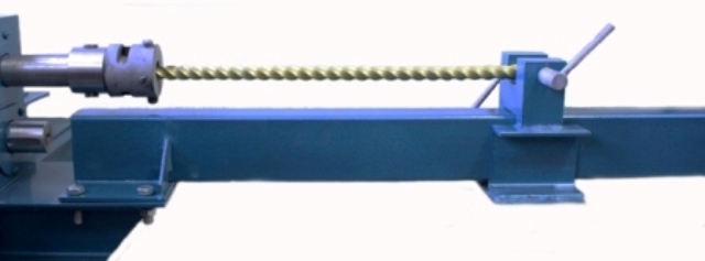
Fig. 1. General machine arrangement
1 – Gear motor; 2 – adjustment bolt; 3 – bed; 4 – rolling module stud; 5 – stop; 6 – nut; 7 – rolling module body; 8 – rolling module roller; 9 – eccentric roll; 10 – grounding point; 11 – mounting plate; 12 – adjustment nut ; 13 - protective cover.
The machine has two working areas and a protective cover.
The reversing switch has two buttons "Forward" and "Backward". Working shaft rotation starts when pressing one of the buttons and stops when it is released.
3. Safety measures when working on the machine
3.1. Read the operating instructions and inspect the machine prior to operation in order to ensure proper and safe use of all its functions.
3.2. The manufacturer has priority on the production of the machine, improves its design and has the right to make changes that not affect its performance.
3.3. Machine operation is allowed with the RCD (residual current device) installed in the network. Electricians having minimum 3 electrical safety qualification must install and connect the machine to the network.
3.4. The machine housing must be grounded using a special conductor with a section not less the phase wire.
3.5. It is prohibited to:
- operate the machine without grounding;
- work with the open circuit breaker cover, side and top panels of the machine;
- move the machine connected to the network;
- put objects and tools on the machine body;
- run the machine at high voltage (more than 10 V);
- operate the machine in explosive or chemically active environment damaging metal and insulation;
- operate the machine in high humidity conditions (more than 80 %), as well as outdoors.
3.6. Take care to protect the machine against blows, overloads, dirt and petroleum product exposure when operating.
3.7. Switch off the machine using the circuit breaker in case of a sudden stop (due to the voltage loss, seizure of moving parts, etc.).
4. Preparing the machine before operation
4.1. In case of machine transportation or storage in high humidity or low temperature conditions, keep it at the temperature of 20 ± 5°C for 5 hours, if you intend to use the machine in a heated room.
4.2 Machine start procedure:
- make sure that the voltage in the mains supply corresponds to the specifications and does not exceed it by more than 10 V;
- set the circuit breaker to the "off" position;
- inspect and ensure the proper insulation of the power cable and connect it to circuit breaker terminals in the correct sequence.
Warning!
The sequence of phase connection must be so that pressing the "Forward" button on the machine panel makes the bushed flange rotating clockwise relative to the side of the machine;
- connect the power cable to the network;
- set the circuit breaker in the "on" position;
- ensure the right rotation of the machine working shaft by pressing the "Forward" and "Backward" buttons.
4.3. Machine stop procedure:
- stop pressing the "Forward" and "Backward" buttons, then the working shaft of the machine will stop immediately;
- remove any metal blanks from machine actuators;
- set the circuit breaker to the "off" position;
- unplug the network cable from the mains.
5. Longitudinal bar stock twisting operation
Follow these steps for longitudinal bar stock twisting:
5.1. Cut the bar (shaped tube, square or strip) to a required length and section (use Steel 0 - 3 only).
5.2. Install additional devices as shown in Fig. 3.
Warning!
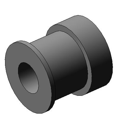
When working with shaped metal tubes install retainer bushing 10 as shown in Fig. 2 using attachment screws 2.
Fig.2 Installation of additional devices for longitudinal shaped tube twisting
1 – retainer bushing, 2 - fixing screws
Fig. 3 Installation of additional devices for longitudinal bar stock twisting
1 – bracket; 2 – screw; 3 – ram; 4 – free-running sleeve; 5 – adapter sleeve; 6 – М16х50 bolt; 7 – М18х1,5 calibration screw
5.3. Set size in sleeve free-running sleeve 4 corresponding to the bar cross-section using screws 7 as shown in Fig. 3. Install the appropriate size in retainer bushing 1 when working with shaped pipes (see Fig. 2) using calibration screws so that to provide a small backlash of a workpiece in the sleeve during the next installation of the workpiece.
5.4. Set ram 5 on the required twisting length and fix it on bracket 1 with bolt 4 as shown in Fig. 4 (tighten with hand or with a wrench), see Fig. 3.
Fig. 4 Workpiece installation for longitudinal bar twisting
1 - longitudinal twisting bracket; 2 - screw; 3 - workpiece; 4- fixing bolt; 5 - ram;
5.5.1. Set the workpiece in a prepared plug (see. p. 3) so that the workpiece has a small backlash around the rotation axis.
5.5.2. Fix the workpiece with screws 2 (the action is performed when longitudinal twisting of square section bars and strips).
5.5.3. Make a visual alignment of the workpiece with screws 7 (Fig. 3.)
5.6.1. Press the "Forward" button.
5.6.2. Count the required number of twisting revolutions of the workpiece and release the "Forward" button.
5.7. Press the "Backward" button to loosen the workpiece (about 1/12 of a turn, or 30 degrees).
5.8. Loosen screws 7 (Fig. 3) and remove the workpiece.
Warning!
A larger number of revolutions may cause workpiece rupture. DO NOT OVERTWIST THE WORKPIECE!
Note: free-running sleeve has about 70-degree travel around its axis for quick installation of the workpiece in the horizontal plane.
6. Operation of spiral cone-shaped item making
Procedure of spiral-cone item making:
6.1. Install devices (Fig. 2, Fig. 3) – "Longitudinal bar stock twisting".
6.2. Cut 8x8 square roll stock or O 8 mm round stock into four workpieces of equal length (?170-250 mm).
6.3. Put them together so that to obtain a 16x16 mm square as shown in Fig. 5 a, 5 b.
Fig. 5а. Fig. 5b.
Fig. 5 Rolled stock workpieces.
а – square section stock; b – round section stock.
6.4. Put ram 3 (Fig. 3.) at a distance of ?160-240 mm from free-running sleeve 7.
6.5. Position the workpiece according to the paragraphs 5.1, 5.2, 5.3.
6.6. 1. Press the "Forward" button.
6.6.2. Count 3-5 revolutions of the workpiece.
6.6.3. Press the "Backward" button.
6.6.4. Perform workpiece untwisting operation by 0.5-1 revolution to obtain the required volume of the spiral-cone item.
6.7. Unlock the module by briefly pressing the "Forward" button, loosen the screws of free-running sleeve 7 (Fig. 3) and fixing sleeve recalibration screws.
6.8. Move ram 3 along bracket 1 (Fig. 3) and take out the obtained item.
7. Strip reinforcing operation (manufacture of clamp blanks)
Procedure of strip reinforcing (manufacture of clamp blanks):
7.1. Cut the workpiece to a required length.
Workpiece requirements:
- rolled stock – 1 to 1.5 mm thickness strip;
- strip reinforcing in one pass – workpiece width is not more than 16..18 mm;
- strip reinforcing in two passes – workpiece width is not more than 20..22 mm.
7.2. Install additional devices as shown in Fig. 6.
7.3. Adjust the position of ways 6, they must be located in line with the upper point of lower roller 3.
7.4. Place the workpiece in the corresponding "pass" between the rolls.
7.5. Press the "Forward" button (hold it until the workpiece release from the opposite side of the rolls).
Fig. 6 Installation of additional devices for strip reinforcing (manufacture of clamp blanks)
1 – top roll, 2 – lower roll; 3 – lower roll fastening bolt; 4 – mounting plate; 5 – rolling module stud; 6 – way; 7 –М16х30 bolt; 8 – 16 washer; 9 – М18х1,5 nut; 10 – М12х30..50 bolt; 11 – washer.
8. Forge-rolling operation
Procedure of forge-rolling operation:
8.1. Cut the workpiece to a required length.
8.2. Install additional devices as shown in Fig. 7.
Fig. 7 Installation of additional equipment for forge-rolling
1 – central roller; 2 – М12х30 bolt; 3 – mounting plate; 4 – way; 5 – М16х30 bolt; 6 – 16 washer; 7 – rolling module stud; 8 – М18х1,5 nut.
8.3. Adjust the position of ways 4 relative to central roller 1 by rotating nuts 8 clockwise or counterclockwise; the distance from the lowest point of central roller 1 to the upper points of ways 4 must be equal to the workpiece size.
The machine forge-rolling method is limited to periodic compression of the workpiece ends with ways 4 by tightening nuts 8 (the optimum number is three turns of the nut in one pass).
Warning!
Exceeding the optimum number of nut revolutions may cause workpiece crushing in the central roller area.
9. Shaped tube reinforcing operation
Procedure of shaped tube reinforcing operation:
9.1. Cut the workpiece to a required length (this operation uses 15x15 or 20x20 shaped tube).
9.2. Install additional devices as shown in Fig. 8.
Fig. 8 Installation of additional devices for shaped tube reinforcing
1 – top roll, 2 – lower roll; 3 – lower roll fastening bolt; 4 – mounting plate; 5 – rolling module stud; 6 – way; 7 – М16х30 bolt; 8 – 16 washer; 9 – М18х1.5 nut; 10 – М12х30..50 bolt; 11 – washer;
9.3. Adjust the position of ways 6 (Fig. 7), they must be adjusted so that the workpiece passing the rolls is located in the horizontal direction.
9.4. Place the workpiece in the corresponding "pass" between rolls 1 and 3 (Fig. 7).
9.5. Press the "Forward" button (hold it until the workpiece releases from the opposite side of the rolls).
10. Bar end rolling into the "Goose feet" shape
Procedure of bar end rolling into the "Goose feet" shape:
10.1. Cut square or round bar stock into the workpiece of a required length (use Steel 0 - 3 only).
10.2. Install additional devices as shown in Fig. 8.
Fig.8 Installation of additional devices for bar end rolling into the "Goose feet" shape
1 – smooth eccentric roller; 2 – grooved eccentric roller; 3 – washer; 4 – М12х30 bolt; 5 – roller fastening bolt; 6 – washer; 7 – stop; 8 – way; 9 – 16 washer; 10 – М16х30 bolt; 11 – М14х16 bolt; 12 – nut.
Note that the right roller of the rolling module must be lifted to the maximum height when mounting additional devices. This is achieved by turning nut 12 clockwise as shown in Fig. 8.
10.3. When devices are mounted, adjust the height of way 8 by rotating nut 12 clockwise or counterclockwise until the way surface is set approximately 3...6 mm below the surface of grooved roller 2 (see Fig. 8).
10.4. Put stop 7 at a distance of 80 mm from the center of the roll rotation axis.
10.5. Place the workpiece end in the window of the gas forge burner (Fig. 9) so that the burner flame completely covers the end of the workpiece.
Fig. 9 Diagram of workpiece installation when heating
1 – forge; 2 – table; 3 – workpiece.
10.6. Heat the metal to the required temperature (3-4 minutes). The temperature of the metal heating can be identified visually: the heated workpiece part has a bright reddish-white glow (1000-1100°C).
10.7. Insert the heated end of the workpiece between eccentric rollers 1, 2 of the rolling module against stop 7. The plane of upper eccentric roller 1 must be located at a maximum distance from the plane of lower eccentric roller 2 (this is set by pressing the "Forward" button).
10.8. Press "Forward" to perform rolling of the heated workpiece end until the workpiece completely releases from rotating eccentric rolls.
10.9. Release the "Forward" button.
Warning!
- Perform all operations with heated metal in special gloves to avoid burns.
- It is strictly prohibited to cool the metal in water or oil after rolling the workpiece to prevent brittleness and shortness of the rolled bar portion. You may immerse the heated metal into a box with sand or earth for cooling.
- It is strictly forbidden to roll the metal not heated to the required temperature.
- Observe the specified mode of operation (rolling: 30 minutes work / 30 minutes break) to avoid removing the hardening (self-tempering) of roll steel.
11. Bar end rolling into the "Faceted pike" shape
Procedure of bar end rolling into the "Faceted pike" shape:
11.1. Cut square or round bar stock into the workpiece of a required length (use Steel 0 - 3 only).
11.2. Install additional devices as shown in Fig. 8 with some changes – use smooth eccentric roller instead of grooved eccentric roller 2.
11.3. Perform steps similar to 10.3 - 10.4.
11.4. Put stop 7 at a distance of 80 mm from the center of the roll rotation axis (the distance varies empirically depending on the required pike parameters)
11.1. Perform steps similar to 10.6 - 10.11.
11.2. Rotate the workpiece by 180° around its axis.
11.5. Perform steps similar to 10.8 -10.11.
Warning!
Perform steps specified for rolling the bar end into the "Faceted pike" shape several times to obtain a more clear form.
Pay attention to safety rules and machine operation instructions described in Section 10.
12. Bar end rolling into the "Domical pike" shape
Procedure of bar end rolling into the "Domical pike" shape:
12.1. Make a "faceted pike" (see Section 11).
12.2. Put stop 7 at a maximum distance from the rolls.
12.3. Place the workpiece end with the item in the furnace according to Sections 10.6, 10.7.
12.4. Perform actions with the workpiece according to Sections 10.8-10.11.
Warning!
Pay attention to safety rules and machine operation instructions described in Section 10.
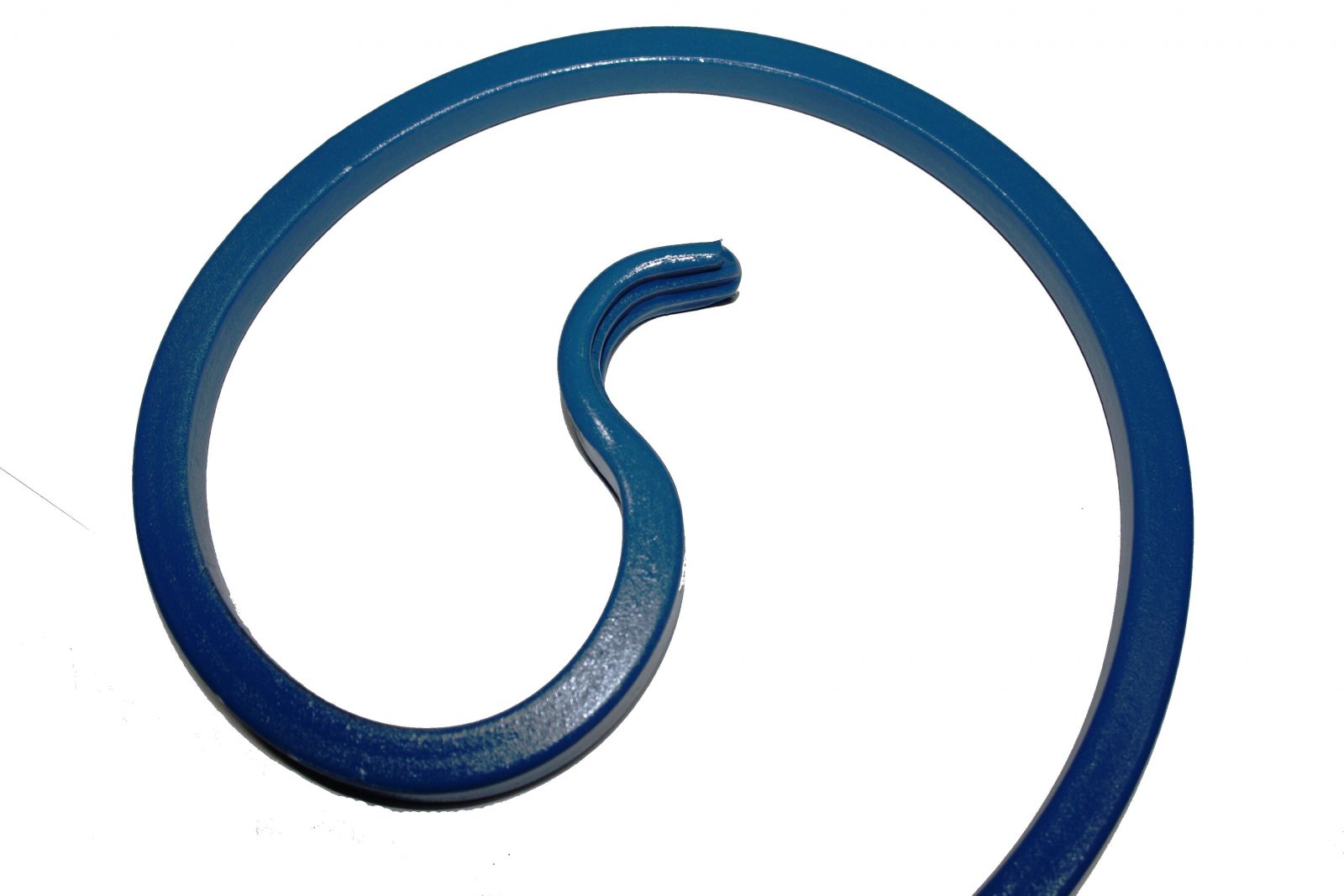
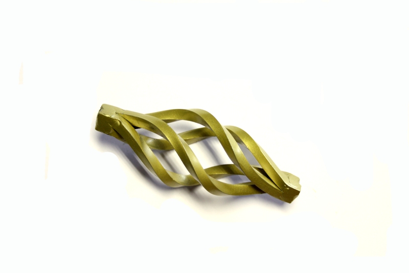
13. Spiral winding of bar stock
13.1. Select the tool for the operation of bar spiral winding depending on the item required:
Table 1. The list of tools and workpieces:
Tool Workpiece
Small template Roll size 200; twisting of the bar stock end
Medium template Roll size 200; twisting of the bar stock end
Assembly template Scroll; twisting of the bar stock end
Mega template Mega scroll, twisting of the bar stock end
13.2. Cut bar stock into the workpiece according to Table 1, 2, 3.
Workpiece requirements:
1.) Use Steel 0 - 3 only.
2.) Rolled stock – shaped tube, round or square bar.
3.) Workpiece end – rolled stock section, crumpled ("goose foot", "fishtail").
Table 2.
Item/Workpiece Size of the workpiece
With claws Without claws Shaped tubes
МEGA scroll 2400 mm 2500 mm 2500 mm
Big scroll 750 mm 850 mm 980 mm
Medium roll 500 mm 600 mm 750 mm
Small roll 400 mm 500 mm 600 mm
The smallest roll 380 mm
Warning!
To avoid template and workpiece damage during the spiral winding install the folding roller bracket strictly in accordance with Table 4 and Fig.12 a , 12 b, 12 c.
Note:
1.) The dimensions in the table are approximate and obtained empirically.
2.) When making a claw, the workpiece length is increased based on the rolled stock section in average by:
Table 3.
Rolled stock section Increase of the workpiece length
claw on one side claw on both sides
10х10 20 40
12х12 30 60
14х14 50 100
13.3.1. Install additional devices as shown in Fig. 11.
13.3.2. Template installation features:
Table 4.
Template Feature
Template Bracket mounting Total stud length, mm
Small Fig. 10.а Fig. 12 а 80
Medium Fig. 10 b Fig. 12 b 80
Assembly Fig. 10 c Fig. 12 c 80
Mega Fig. 10 d Fig. 12 d 80
Fig. 10.а Small template; Fig. 10. b Medium template;
Fig. 10.c Assembly template; Fig. 10. d Mega template.
Fig. 11. Installation of additional devices for bar spiral winding
1 – bushed flange; 2 – template; 3 – bracket; 4 – folding roller; 5 – M16 nut; 6 – 16 washer; 7 – pin; 8 – stud; 9 – M12 nut; 10 – 12 washer.
Fig. 12. а Bracket mounting; Fig. 12. b Bracket mounting;
Fig. 12. c Bracket mounting.
13.3.3.1. Template installation (small, medium, assembly) according to Fig. 11, Table 4:
1. Install studs 8 on bushed flange 1.
2. Set template 2.
3. Fasten it through washer 10 and nut 9.
4. Set bracket 3.
13.3.3.2. Mega template installation according to Table 4:
1. Install studs 8 on bushed flange 1, Fig 13.
Рис. 13 Installation of studs on the bushed flange
1 – bushed flange; 8 – stud.
2. Install mega template 2 and the central part of assembly template 12 as shown in Fig. 14.
Fig. 14. Mega template installation
2 – mega template; 9 – M12 nut; 10 – 12 washer; 12 – central part of assembly template.
3. Fix the assembly with washer 10 and nut 9 according to Fig. 16.
4. Install bracket 3 (Fig. 12).
13.4.1. Set thrust screws 1 of template 2 corresponding to the thickness of workpiece end 3 as shown in Fig. 15.
Fig. 15. Workpiece installation when bar end spiral winding
1 – М14х27 screw; 2 – template; 3 – workpiece.
Warning!
Leave a small gap for easy installation and removal of the workpiece during the operation when setting the thrust screws of the template corresponding to the workpiece end thickness.
13.4.2. Set the initial template position using the "Forward", "Backward" buttons so that the bar workpiece can freely enter the template groove in horizontal position.
13.5.1. Insert the workpiece into the template groove.
13.5.2. Press the "Forward" button while supporting the free part of the workpiece with hand. Make sure that the free part of the workpiece is located on the support roller in the template rotation plane during the spiral twisting.
Warning!
Mark the end position of twisting on the bushed flange relative to the shaft rotation center in order to make items of the same size.
13.5.3. Loosen the pressure of the free workpiece part on the support roller by pressing the "Backward" button.
13.5.4. Remove the workpiece from the template.
Warning!
Make the workpiece on the assembly template prior to start working with the mega template.
14. Operation with turn-in device
The turn-in device is used for turning in the scroll ends after the "Goose feet" operation.
Procedure of item turning-in:
14.1. Mount additional devices as shown in Fig. 16.
14.2. Install scroll 6 into the turn-in device according to Fig. 16.
14.3. Press the "Forward" button and hold it until the required twisting of the scroll end is achieved.
14.4. Press "Backward" to loosen the action of the workpiece on the thrust roller.
Fig. 16 Turn-in device installation
1 – bushed flange; 2 – tail; 3 – bushing; 4 – screw; 5 – thrust roller; 6 – scroll workpiece with the end passed the "Goose feet" operation
15. Ring making operation
Ring making procedure:
15.1. Cut the workpiece to a required length.
Note: rolled stock used for this operation – square and round bars, shaped tubes.
15.2. Install additional devices as shown in Fig. 17.
Note: installation of the devices is similar for different ring diameters; with small faceplate – O90 mm ring, with large faceplate– O120 mm ring.
15.3. Set workpiece 10 as shown in Fig.17.
15.4. Press the "Forward" button and hold it until the end of the ring winding (maximum number of turns when making rings with the small or large faceplate is 3-4 turns).
Fig. 17 Installation of additional devices for ring making
1 – bushed flange; 2 – washer; 3 – faceplate; 4 – thrust roller; 5 – long stud (110 mm length); 6 – stud (80 mm length); 7 – M12 nut; 8 – 12 washer; 9 – М16х1.5 thrust screw; 10 – workpiece.
А – seat for limit screw 9 when working with the small faceplate;
Б – seat for limit screw 9 when working with the big faceplate.
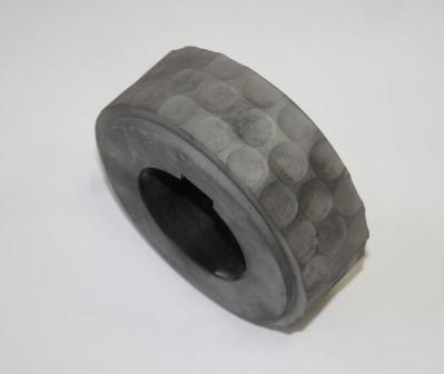
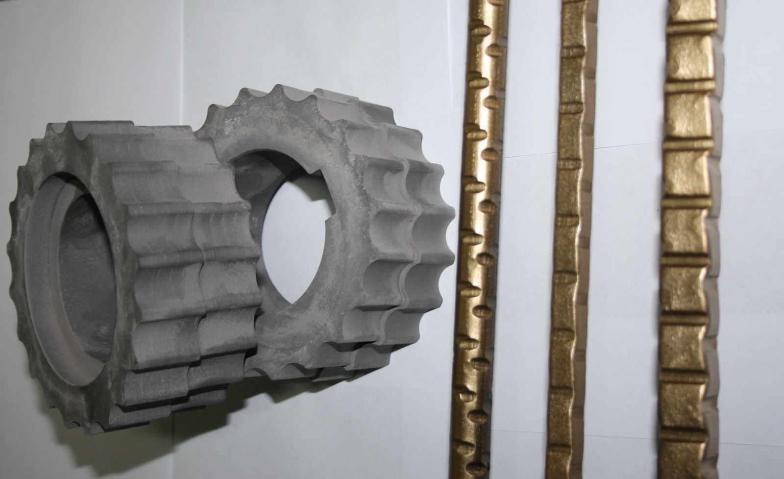
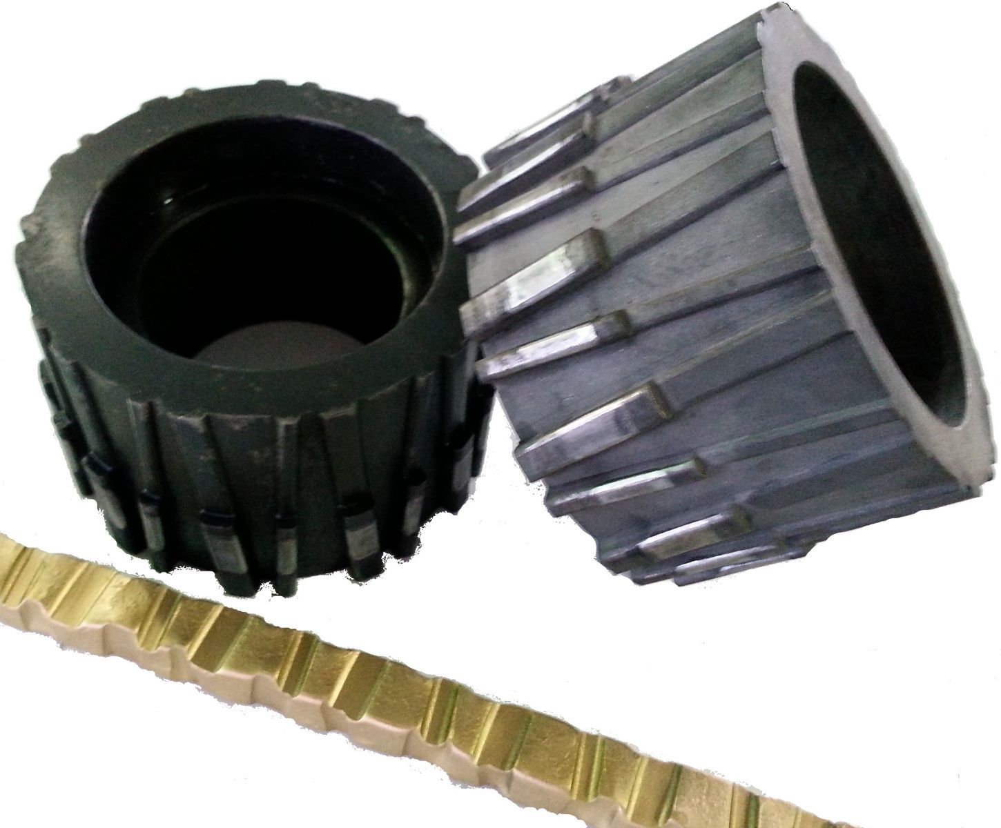
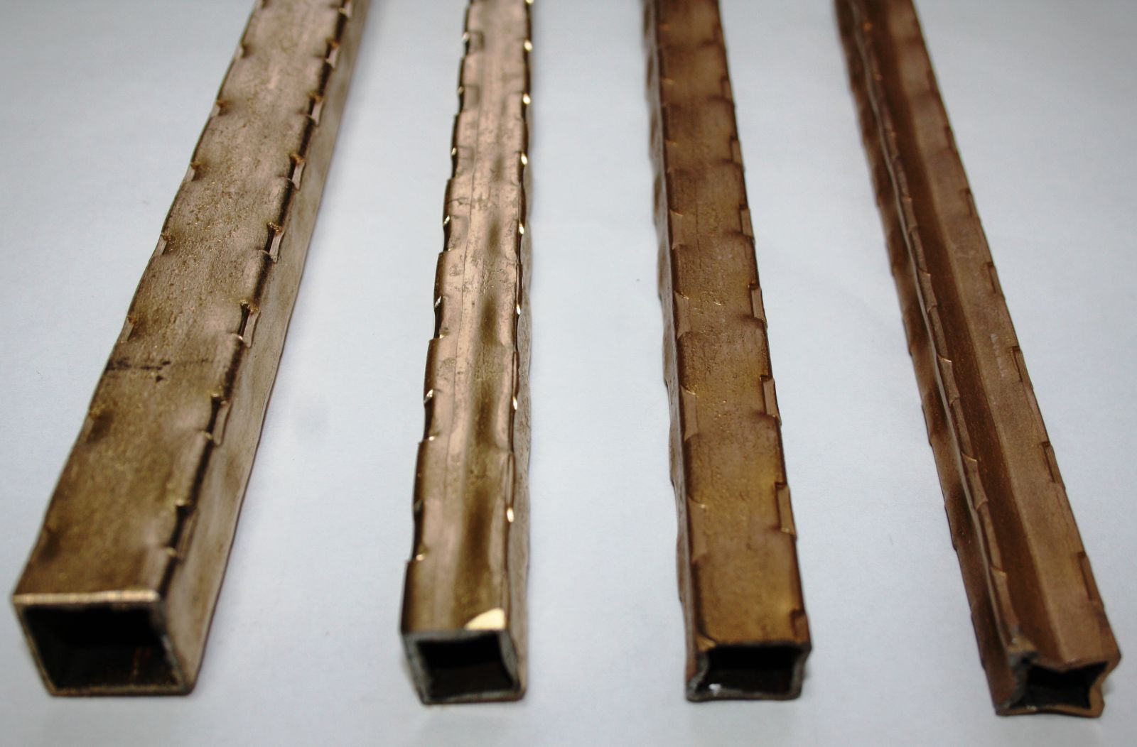
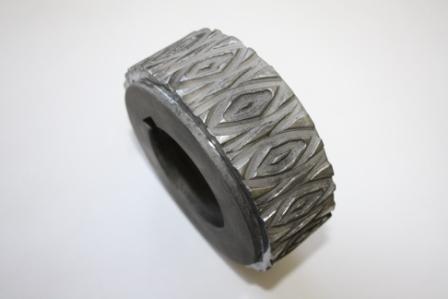
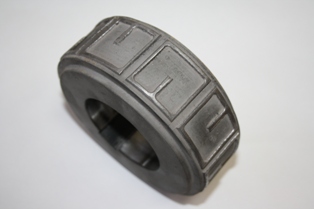
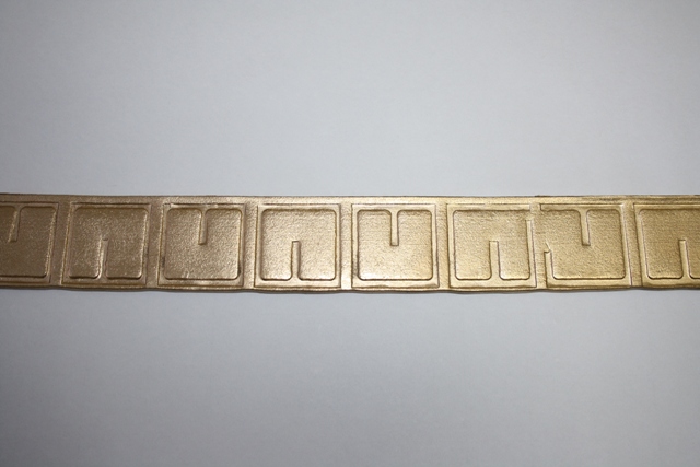
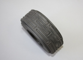
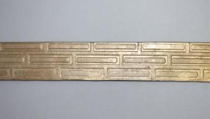
16. Application of decorative squeezes on rolled stock
Description of the unit mounting:
1. Mount guide rollers 1.
2. Install rolls 2 (in pair).
3. Adjustment the ways relative to the strip rolled.
Fig. 18 Installation of the device for decorative squeeze application on rolled stock
1 – guide rollers; 2-smooth roll, 3 – textured roll; 4 – М18х1.5 nut; 5 – roll fastening bolt; 6 – washer; 7 – М12х30 bolt; 8 - washer.
After installation of the unit press the "Forward" button and hold it until the end of the decorative squeeze application on the workpiece.
Similar operations are performed for applying textures to square and round rolled stock.
17. Maintenance of the machine
Check the following during the machine operation:
16.1 Grounding wire and power supply cable integrity – daily;
16.2. Security of machine actuators – daily;
16.3. Wire insulation resistance (not less than 2.5 M?) – twice a year;
16.4. Availability and level of oil in the gearbox case ("I-20" oil) – every six months.
16.5 Shaft bearings and gear wheels of the rolling module for adequate greasing ("Litol-24" lubricant injection) – twice a year.
18. Manufacturer's warranty
1. The warranty period is 12 (twelve) months for mechanical parts and tools for hot and cold forging (dies, templates, rolls, rollers, clamps, faceplates, etc.) from the date of Equipment transfer to the Buyer.
2. The manufacturer assumes no warranty if the Buyer fails to observe equipment operation rules provided in this manual.
3. The quality of the delivered Equipment meets the requirements of GOST and TU of the Russian Federation approved for this type of equipment, as well as certificates of compliance certificates and technical certificates.
4. The Seller is responsible for Equipment defects if the Buyer proves that they were found before the Equipment was transferred to the Buyer or they were caused by the reasons took place up to that point. In this case, the Seller agrees to replace the Equipment of inadequate quality within the period specified in the additional agreement signed by the Parties.
5. The Seller guarantees the quality and completeness of the delivered Equipment according to the terms indicated in the technical certificate for the Equipment supplied. If any Equipment defects caused by the Seller are identified within the warranty period, the Seller is bound to recover the equipment on the Buyer's request or, if necessary, to transport the defective equipment by its own efforts and expenses within 60 days from the date of the notification receipt. Transport costs in this case are divided equally.
6. The Seller agrees to replace worn or broken machine components during the warranty period. The Seller shall be responsible for the costs associated with delivery of components to the Buyer. The period of component delivery is 2 (two) weeks.
Appendix 1
Master-2U electrical circuit
Circuit diagram for the machine with 380 V power supply
Circuit diagram of machine with power supply 220 V
Appendix 2
USER MEMO FOR GAS FORGE
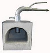
Fig. 8 General gas forge diagram
1 – Table; 2 – Forge, 3 – Nozzle; 4 – Adjustment bolt; 5 – Workpiece.
1. Connect the gas forge burner in the following order:
- Direct burner inlet is designed to supply propane from the cylinder (or central gas main). It is performed by attaching a hose to the burner (using a nipple) and to the cylinder (using a special adjustable propane reducer).
- Side burner inlet is intended for feeding compressed air from the compressor (250-400 L/min capacity) or central compressed-air main through the hose.
- Furnace burner is adjustable in its vertical position depending on the torch length (fixing with side screws).
2. Operating procedure using the gas forge:
- Install the furnace on the furnace table, adjust the height of the torch and fix it with bolts.
- Open two ejector holes on the gas burner inlet (move the rubber ring to the side).
- Ignite a piece of paper (or wooden stick) and put it in the furnace chamber with the gas and compressed air stopped.
- Open the valve with gas (0.05 to 0.1 atm).
- Supply compressed air after burner ignition.
- Adjust the torch flame (bright blue).
- Adjust the flame by adjusting the gas or compressed air flow rate after establishing a stable torch flame and torch heating (1-2 min).
- Put the ends of the workpieces (round, square bars) in the furnace chamber for 3-4 minutes until the desired temperature is reached (800-900 ?C to yellow or bright orange color).
- Close the propane and compressed air supply inlet when the gas forge operation is finished.
Warning! Follow safety rules for using of gas appliances!


.JPG)
.JPG)
.jpg)